
Foot brake valve with integrated pressure limit function

A technology of foot brake valve and function, which is applied in the field of commercial vehicle braking system and can solve the problem of small air pressure controllable range

Pending Publication Date: 2018-05-04
克诺尔商用车系统(重庆)有限公司
View PDF0 Cites 0 Cited by
  • Summary
  • Abstract
  • Description
  • Claims
  • Application Information

AI Technical Summary

Problems solved by technology

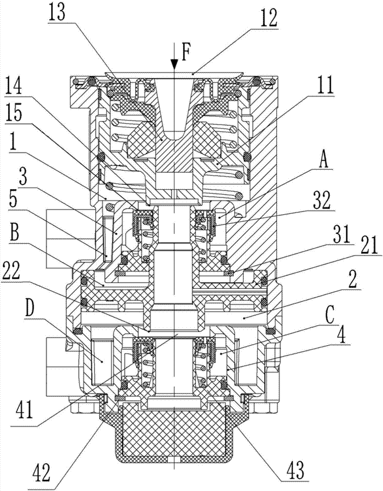
After the upper cavity fails (that is, no gas enters the upper cavity), when the brakes are applied (force F is applied to the upper piston), the upper piston moves downward until it withstands the lower piston, and the lower piston moves downward, closing the lower valve The exhaust port 22, the second on-off valve 43 is opened, the air pressure from the second air inlet reaches the D air chamber from the C air cavity, and the second air outlet is output; in the above process, the second on-off valve 43 is fully dependent on the force of the foot To open, the force of the D air chamber will give a great reaction force to the foot after the force rises; so after the upper chamber fails, the controllable range of the output air pressure of the D air chamber is small

Method used


Image

  • Foot brake valve with integrated pressure limit function
  • Foot brake valve with integrated pressure limit function

Examples


Embodiment Construction

[0034] The present invention will be described in further detail below by means of specific embodiments:

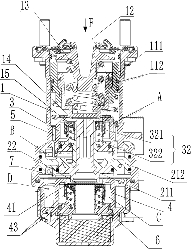
[0035]The reference signs in the accompanying drawings of the specification include: upper cavity 1, upper piston 11, upper outer piston 111, upper inner piston 112, stepping plate 12, pushing column 13, first support plate 31, first switch valve 32, upper Valve body 321, lower valve body 322, upper valve exhaust port 14, communication port 15, lower cavity body 2, lower piston 21, lower inner piston 211, lower outer piston 212, lower valve exhaust port 22, communication cavity 3, Valve body cavity 4 , through hole 41 , second support plate 42 , second switch valve 43 , communication pipe 5 , support plate 6 , and blocking flange 7 .

[0036] Such as figure 2 Shown, in order to achieve the above object, basic scheme of the present invention is as follows:

[0037] A foot brake valve with integrated pressure limiting function, comprising a valve body, an upper cavity 1,...


PUM


Abstract

The invention relates to the technical field of brake systems of commercial vehicles, in particular to a foot brake valve with an integrated pressure limit function. The foot brake valve comprises a valve. An upper piston which can be driven by a push cylinder to descend is arranged on the upper portion of the valve, a lower piston is slidably connected with the lower portion of the valve, the upper piston comprises an upper inner piston and an upper outer piston, and the upper outer piston is slidably connected with the upper portion of the valve; the upper inner piston is slidably connectedinto the upper outer piston; elastic components are arranged between the push cylinder and the upper inner piston, the lower portion of the upper inner piston extends out of the upper outer piston, and the upper inner piston can upwardly move under the effect of the pressures of air in an upper cavity; the upper inner piston can be in contact with the lower piston. According to the scheme, the foot brake valve has the advantages that the foot brake valve can have the pressure limit function, and accordingly output pressures are assuredly lower than input pressures.

Description

technical field [0001] The invention relates to the technical field of commercial vehicle brake systems, in particular to a foot brake valve with integrated pressure limiting function. Background technique [0002] Braking, also known as braking, refers to the action of stopping or reducing the speed of running locomotives, vehicles and other means of transportation or machinery. A foot brake valve is disclosed in the prior art such as figure 1 As shown, a valve body is included, and an upper cavity 1 , a lower cavity 2 and a communication cavity 3 are arranged in the valve body, and the upper cavity 1 and the lower cavity 2 are communicated through the communication cavity 3 . An upper piston 11 is slidably connected in the upper cavity 1, and a stepping plate 12 is provided on the top of the upper piston 11. The stepping plate 12 is provided with a push column 13 for pushing the upper piston 11 to move downward along the inner wall of the upper cavity 1, and pushes The p...

Claims


Application Information

Patent Timeline
IPC IPC(8): B60T15/04
CPCB60T15/041
Inventor 唐光辉陈洪刚李津豪
Owner 克诺尔商用车系统(重庆)有限公司
Learn More