Mechanical milling machine with clamping function
A technology of clamping mechanism and milling machine, which is applied in the direction of metal processing machinery parts, clamping, manufacturing tools, etc., can solve the problems of reducing work efficiency, time-consuming and labor-intensive, and the effect of clamping is not very ideal, so as to improve work efficiency and effect Good results
- Summary
- Abstract
- Description
- Claims
- Application Information
AI Technical Summary
Problems solved by technology
Method used
Image
Examples
Embodiment 1
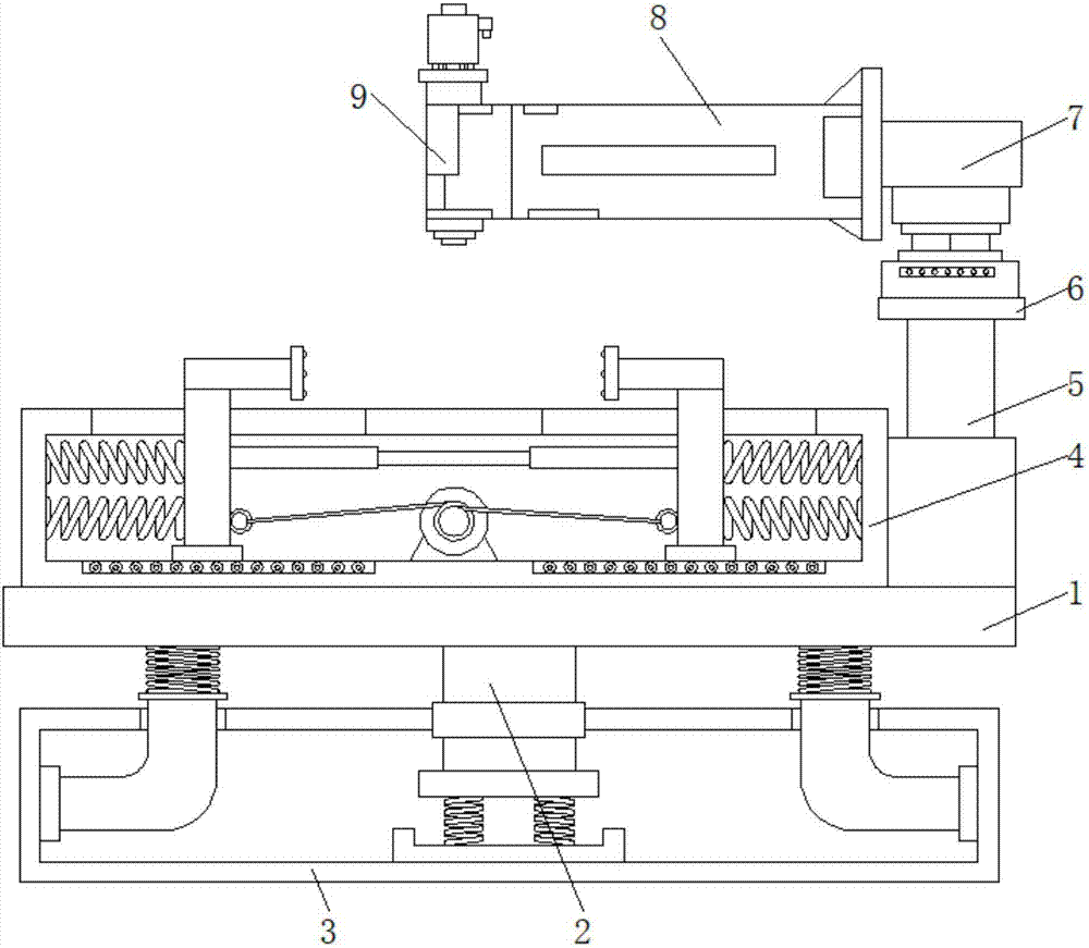
[0033] A mechanical milling machine with a clamping function, comprising a support platform 1, the middle part of the bottom of the support platform 1 is fixedly connected with a support column 2, the bottom of the support column 2 is fixedly connected with a shock absorbing mechanism 3, and the top of the support platform 1 is fixedly connected with a clamp The tightening mechanism 4, the top of the support table 1 is fixedly connected with the electric push rod 5 located on the right side of the clamping mechanism 4, the top of the electric push rod 5 is fixedly connected with the installation block 6, and the top of the installation block 6 is fixedly connected with the milling machine body 7, One side of the milling machine body 7 is fixedly connected with a fixed column 8 , and one side of the fixed column 8 is fixedly connected with a milling head 9 .
Embodiment 2
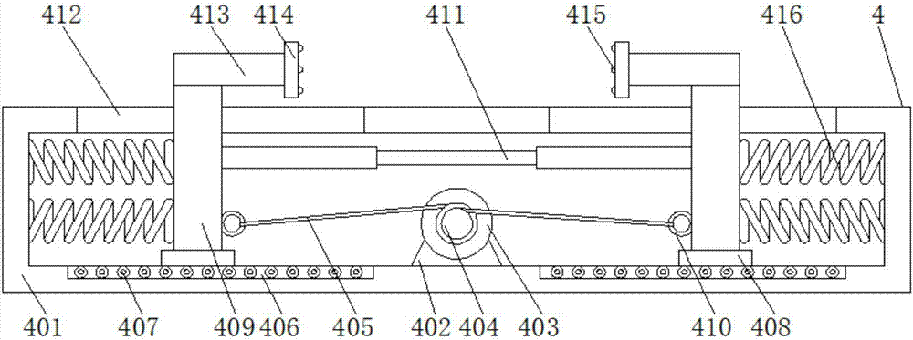
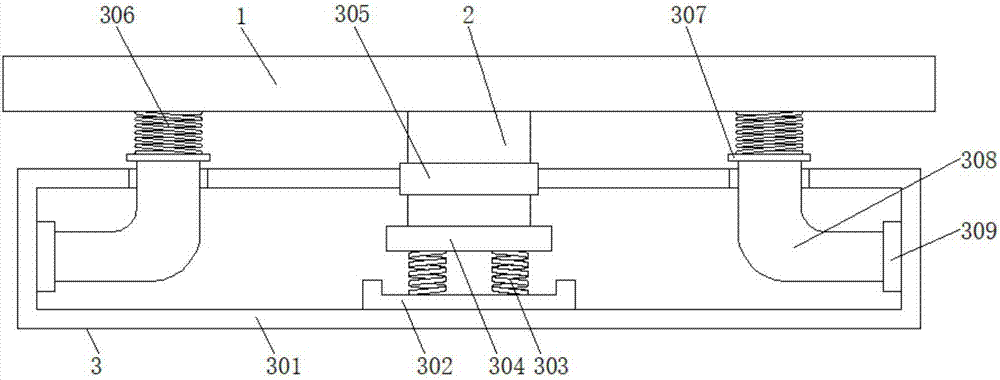
[0035] A mechanical milling machine with a clamping function, comprising a support platform 1, the middle part of the bottom of the support platform 1 is fixedly connected with a support column 2, the bottom of the support column 2 is fixedly connected with a shock absorbing mechanism 3, and the top of the support platform 1 is fixedly connected with a clamp The tightening mechanism 4, the top of the support table 1 is fixedly connected with the electric push rod 5 located on the right side of the clamping mechanism 4, the top of the electric push rod 5 is fixedly connected with the installation block 6, and the top of the installation block 6 is fixedly connected with the milling machine body 7, One side of the milling machine body 7 is fixedly connected with a fixed column 8 , and one side of the fixed column 8 is fixedly connected with a milling head 9 .
[0036] The clamping mechanism 4 includes a clamping seat 401, the middle part of the inner bottom wall of the clamping s...
Embodiment 3
[0038] A mechanical milling machine with a clamping function, comprising a support platform 1, the middle part of the bottom of the support platform 1 is fixedly connected with a support column 2, the bottom of the support column 2 is fixedly connected with a shock absorbing mechanism 3, and the top of the support platform 1 is fixedly connected with a clamp The tightening mechanism 4, the top of the support table 1 is fixedly connected with the electric push rod 5 located on the right side of the clamping mechanism 4, the top of the electric push rod 5 is fixedly connected with the installation block 6, and the top of the installation block 6 is fixedly connected with the milling machine body 7, One side of the milling machine body 7 is fixedly connected with a fixed column 8 , and one side of the fixed column 8 is fixedly connected with a milling head 9 .
[0039] The clamping mechanism 4 includes a clamping seat 401, the middle part of the inner bottom wall of the clamping s...
PUM
 Abstract
Description
Claims
Application Information
 - R&D Engineer
- R&D Manager
- IP Professional
- Industry Leading Data Capabilities
- Powerful AI technology
- Patent DNA Extraction
Browse by: Latest US Patents, China's latest patents, Technical Efficacy Thesaurus, Application Domain, Technology Topic, Popular Technical Reports.
© 2024 PatSnap. All rights reserved.Legal|Privacy policy|Modern Slavery Act Transparency Statement|Sitemap|About US| Contact US: help@patsnap.com


