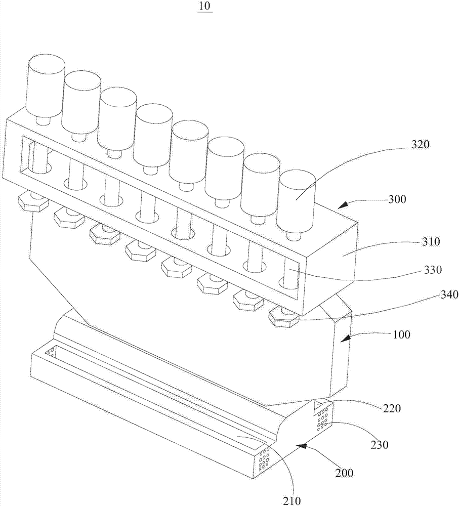
Air blowing and removing device

A cleaning device, a technology for blowing air pipes, applied in the direction of removing smoke and dust, using gas flow cleaning methods, cleaning methods and utensils, etc.

Inactive Publication Date: 2018-05-01
惠州市威帝食品科技有限公司
View PDF0 Cites 3 Cited by
  • Summary
  • Abstract
  • Description
  • Claims
  • Application Information

AI Technical Summary

Problems solved by technology

[0005] The purpose of the present invention is to overcome the deficiencies in the prior art, to provide an air blowing and removing device that is not prone to sticky dust or water drops, and can achieve a higher degree of cleanliness

Method used


Image

  • Air blowing and removing device

Examples


Embodiment Construction

[0021] In order to facilitate the understanding of the present invention, the present invention will be described more fully below with reference to the associated drawings. Preferred embodiments of the invention are shown in the accompanying drawings. However, the present invention can be embodied in many different forms and is not limited to the embodiments described herein. On the contrary, the purpose of providing these embodiments is to make the disclosure of the present invention more thorough and comprehensive.

[0022] It should be noted that when an element is referred to as being “fixed” to another element, it can be directly on the other element or there can also be an intervening element. When an element is referred to as being "connected to" another element, it can be directly connected to the other element or intervening elements may also be present. The terms "vertical," "horizontal," "left," "right," and similar expressions are used herein for purposes of ill...


PUM


Abstract

The invention discloses an air blowing and removing device. The air blowing and removing device comprises a cleaning mounting plate body, a cleaning mounting positioning seat and multiple air blowingassemblies, wherein one end of the cleaning mounting plate body is installed on the cleaning mounting positioning seat, and the multiple air blowing assemblies are arranged at the end, away from the cleaning mounting positioning seat, of the cleaning mounting plate body. According to the air blowing and removing device, the cleaning mounting plate body, the cleaning mounting positioning seat and the multiple air blowing assemblies are arranged, when the cleaning mounting plate body needs to be cleaned, air is conveyed through air blowing controllers and air blowing pipelines, and then air injection operation is carried out through air blowing nozzles so that dust on the cleaning mounting plate body can be removed; and in the same way, the air is conveyed through the air blowing controllersand the air blowing pipelines, and then air injection operation is carried out through the air blowing nozzles so that water drops on the cleaning mounting plate body can be removed, and therefore the purpose of removing by air blowing is achieved, the manual work mode is replaced, and the working efficiency and the cleanliness are effectively improved.

Description

technical field [0001] The invention relates to the technical field of cleaning devices, in particular to an air blowing cleaning device. Background technique [0002] Currently, walls are an important part of buildings. Its function is to bear weight, enclose or separate space. The wall is divided into load-bearing wall and non-load-bearing wall according to the force and material of the wall, and divided into solid wall, sintered hollow brick wall, hollow wall and composite wall according to the wall structure. [0003] Walls are divided into load-bearing walls and non-load-bearing walls according to the different stress conditions of the structure. Walls that directly bear the load from the upper roof and floor are called load-bearing walls; walls that do not bear the upper load are called non-load-bearing walls, and non-load-bearing walls include partition walls, filling walls and curtain walls. The partition wall plays the role of separating the indoor space and shou...

Claims


Application Information

Patent Timeline
IPC IPC(8): B08B5/02B08B15/04
CPCB08B5/02B08B15/04
Inventor 严国伟
Owner 惠州市威帝食品科技有限公司
Why Eureka
Try Eureka