
Two-point modulation transmitter calibration circuit and calibration method thereof

A technology for calibrating circuits and transmitters, applied in the field of transmitters, can solve the problems of low-pass branch, high-pass branch delay and poor gain matching, etc., and achieve the effect of high-quality all-pass transmission

Active Publication Date: 2018-04-27
NATIONZ TECH INC
View PDF5 Cites 18 Cited by
  • Summary
  • Abstract
  • Description
  • Claims
  • Application Information

AI Technical Summary

Problems solved by technology

[0008] The technical problem to be solved by the present invention is: when the signal is transmitted in the high- and low-pass branches, the delay and gain matching of the low-pass and high-pass branches are not good due to changes in technology, voltage and temperature

Method used


Image

  • Two-point modulation transmitter calibration circuit and calibration method thereof
  • Two-point modulation transmitter calibration circuit and calibration method thereof
  • Two-point modulation transmitter calibration circuit and calibration method thereof

Examples


specific Embodiment

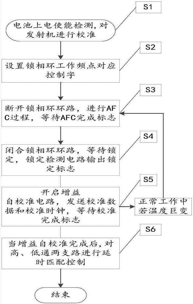
[0057] Step Ⅰ: Battery power-on enable detection. After power-on is detected, the transmitter should be ready to transmit. Before signal communication, the transmitter needs to be calibrated to ensure communication quality.

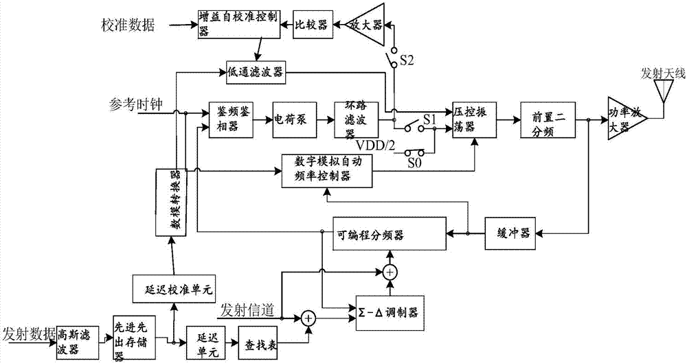
[0058] Step Ⅱ: If figure 1 As shown, set the integer frequency division ratio and fractional frequency division ratio control word corresponding to the operating frequency of the phase-locked loop through the RF Channel, and enable the module of the open-loop path of the phase-locked loop.

[0059] Step Ⅲ: If figure 1 As shown, closing S0 and opening S1 cuts off the PLL loop, and at the same time opens S2 to carry out the automatic frequency control (AFC) process. At this time, the loop is formed by VCO, Pre-Divider 2, Buffer, and Digital / Analog AFC The circuit realizes the rough adjustment of the working frequency of the phase-locked loop, so that the phase-locked loop is locked within a certain error range of the working frequency point, and waits fo...


PUM


Abstract

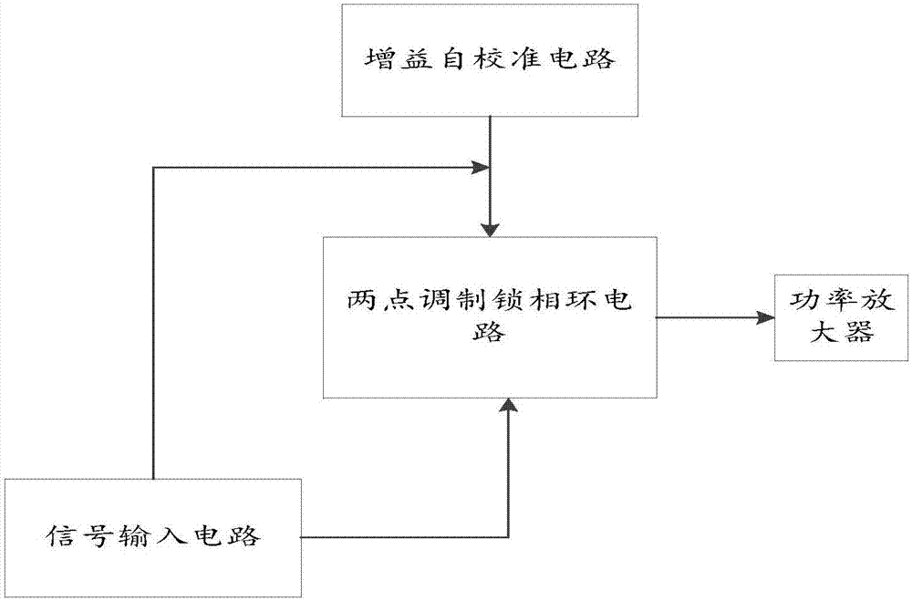
The invention relates to a two-point modulation transmitter calibration circuit and a calibration method thereof. The circuit comprises a two-point modulation phase-locked loop system, a signal inputcircuit, a power amplifier and a gain self-calibration circuit. The method comprises the following steps of transmitting calibration data after a phase-locked loop is locked at a working frequency, computing a gain difference of a high path and a low path through the gain self-calibration circuit by taking a low-pass branch as a reference, utilizing a special calibration time sequence to adjust control words of a low-pass filter in an anti-clockwise manner, changing output amplitude of a digital-to-analog converter to achieve gain matching of the two branches, and configuring a delay control word to complete a calibration process. According to the two-point modulation transmitter calibration circuit and the calibration method thereof, calibration of delay matching can be realized, a function of automatic gain calibration is provided, and the problems that the traditional two-point modulation frequency offset calibration has large resource consumption and long calibration time, and thefrequency offset is caused by huge temperature change are solved.

Description

technical field [0001] The invention relates to a transmitter suitable for low power consumption, in particular to a two-point modulation transmitter calibration circuit and calibration method. Background technique [0002] There are three main types of direct transmitters based on phase-locked loops: (1) out-of-band transmitters based on phase-locked loops; (2) in-band transmitters based on phase-locked loops; (3) two-point transmitters based on phase-locked loops Modulate the transmitter. The two-point modulation transmitter based on the phase-locked loop is more suitable for high-quality transmission and low power consumption because it overcomes the weak anti-interference ability of the out-of-band transmitter and breaks the limitation of the in-band transmitter by the bandwidth of the phase-locked loop. wireless communication device. [0003] The most common architectures for phase-locked loop-based two-point modulated transmitters, such as Figure 7 As shown, the two...

Claims


Application Information

Patent Timeline
Patent Type & Authority Applications(China)
IPC IPC(8): H04B17/11
CPCH04B17/11H03L7/099
Inventor 赵辉何国军曾军
Owner NATIONZ TECH INC
Learn More