
Motor rotor iron core, motor rotor, motor and washing machine

A motor rotor and rotor core technology, which is applied in the fields of motors and washing machines, motor rotor cores, and motor rotors, can solve problems such as difficulty in ensuring the roundness of the iron core, different radial positions of permanent magnets, and uniformity of the motor air gap. Achieve the effect of preventing radial position difference and ensuring rigidity

Pending Publication Date: 2018-04-27
ZHUHAI GREE REFRIGERATION TECH CENT OF ENERGY SAVING & ENVIRONMENTAL PROTECTION
View PDF2 Cites 5 Cited by
  • Summary
  • Abstract
  • Description
  • Claims
  • Application Information

AI Technical Summary

Problems solved by technology

[0005] Therefore, the technical problem to be solved by the present invention is to overcome the defect that the roundness of the iron core formed by the motor rotor core in the prior art is difficult to guarantee, which causes the radial position of the permanent magnet to be different and affects the uniformity of the air gap of the motor, thereby providing a Motor rotor core, motor rotor, motor and washing machine

Method used


Image

  • Motor rotor iron core, motor rotor, motor and washing machine
  • Motor rotor iron core, motor rotor, motor and washing machine
  • Motor rotor iron core, motor rotor, motor and washing machine

Examples


Embodiment Construction

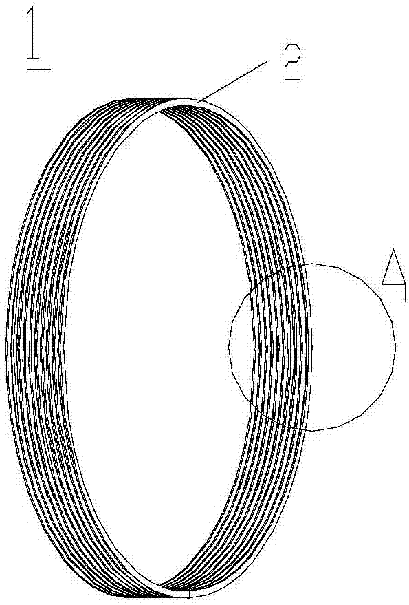
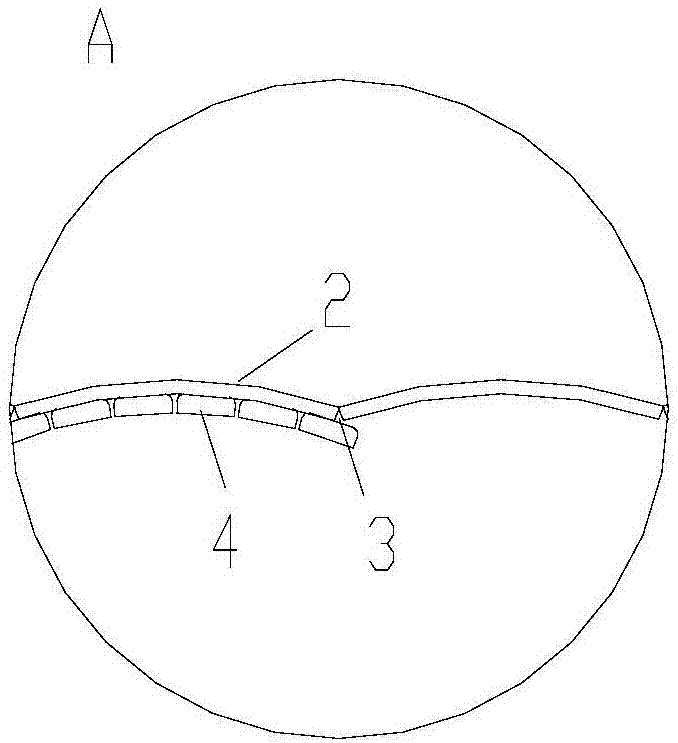
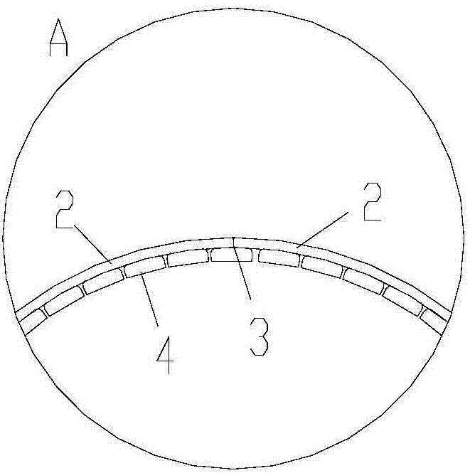
[0063] Such as Figure 1-2c As shown, the present invention provides a motor rotor iron core 1, which includes:

[0064] The rotor core 1 is formed by successively connecting and winding a plurality of strip-shaped punching sheets 2, and when the plurality of strip-shaped punching sheets 2 are unfolded, there is a notch between two adjacent strip-shaped punching sheets 2 3. To enable multiple segments of the strip-shaped punching sheet 2 to be bent to form a circular ring structure when wound to accommodate magnets (preferably permanent magnets) arranged in the circular ring structure.

[0065] The rotor core is formed by successively connecting and winding a plurality of strip-shaped punching sheets, and when the plurality of strip-shaped punching sheets are unfolded, there are notches between the two adjacent strip-shaped punching sheets, so that the When the strip punches are wound, they can be bent to form a circular ring structure to accommodate the magnets arranged in the cir...


PUM


Abstract

The invention provides a motor rotor iron core, a motor rotor, a motor and a washing machine. The motor rotor iron core (1) is formed by successive connection and winding of a plurality of bar-shapedpunching sheets (2); when the multiple bar-shaped punching sheets (2) are unfolded, a notch (3) is formed between each two adjacent bar-shaped punching sheets (2), so that the plurality of bar-shapedpunching sheets (2) are bent in a winding state to form a circular ring structure so as to accommodate a magnet in the circular ring structure. Therefore, the plurality of bar-shaped punching sheets with notches are bent to form the circular structure to form a cylindrical rotor iron core by winding moulding, so that the roundness of the rotor iron core is ensured and natural centering of the rotor is realized; and thus a phenomenon that the gas gap uniformity of the motor is affected by different radial positions of permanent magnets is avoided.

Description

Technical field [0001] The invention belongs to the technical field of motors, and specifically relates to a motor rotor iron core, a motor rotor, a motor and a washing machine. Background technique [0002] The existing patent number CN102403810B discloses a direct drive motor rotor of a washing machine. The iron core of the rotor is formed by cutting a steel pipe or a bent steel plate. This structure can form the magnetic circuit of the rotor while ensuring the housing Stiffness. However, the iron core is integrally wound, which easily causes the iron loss of the rotor iron core to increase; in addition, it is difficult to reshape the cut or crimped steel plate after forming, which makes it difficult to ensure the roundness of the iron core of the structure, which directly causes the permanent magnet to radially The position is different, and the air gap of the motor is uniform. In addition, the radiating holes and radiating blades of the rotor are punched out of circular ste...

Claims


Application Information

Patent Timeline
Patent Type & Authority Applications(China)
IPC IPC(8): H02K1/22H02K1/27H02K7/04H02K1/32H02K5/16H02K9/06
CPCH02K1/22H02K1/27H02K1/2786H02K1/32H02K5/16H02K7/04H02K9/06H02K2213/03
Inventor 胡余生钟成堡焦雷刘伟健谢芳肖智勇张智超
Owner ZHUHAI GREE REFRIGERATION TECH CENT OF ENERGY SAVING & ENVIRONMENTAL PROTECTION
Learn More