
Hot air utilizing device realizing high-efficiency utilization of energy

A technology of energy and hot air, applied in household heating, application, heating fuel, etc., can solve the problem of low heat utilization rate, achieve the effect of optimized and reasonable structural design, and improve recycling rate

Inactive Publication Date: 2018-04-27
SINOBIOWAY DINGHE ENVIRONMENTAL PROTECTION CO LTD
View PDF0 Cites 2 Cited by
  • Summary
  • Abstract
  • Description
  • Claims
  • Application Information

AI Technical Summary

Problems solved by technology

However, in the removal process, pollutant pretreatment is required, and the heat utilization rate contained in it is low

Method used


Image

  • Hot air utilizing device realizing high-efficiency utilization of energy

Examples


Embodiment Construction

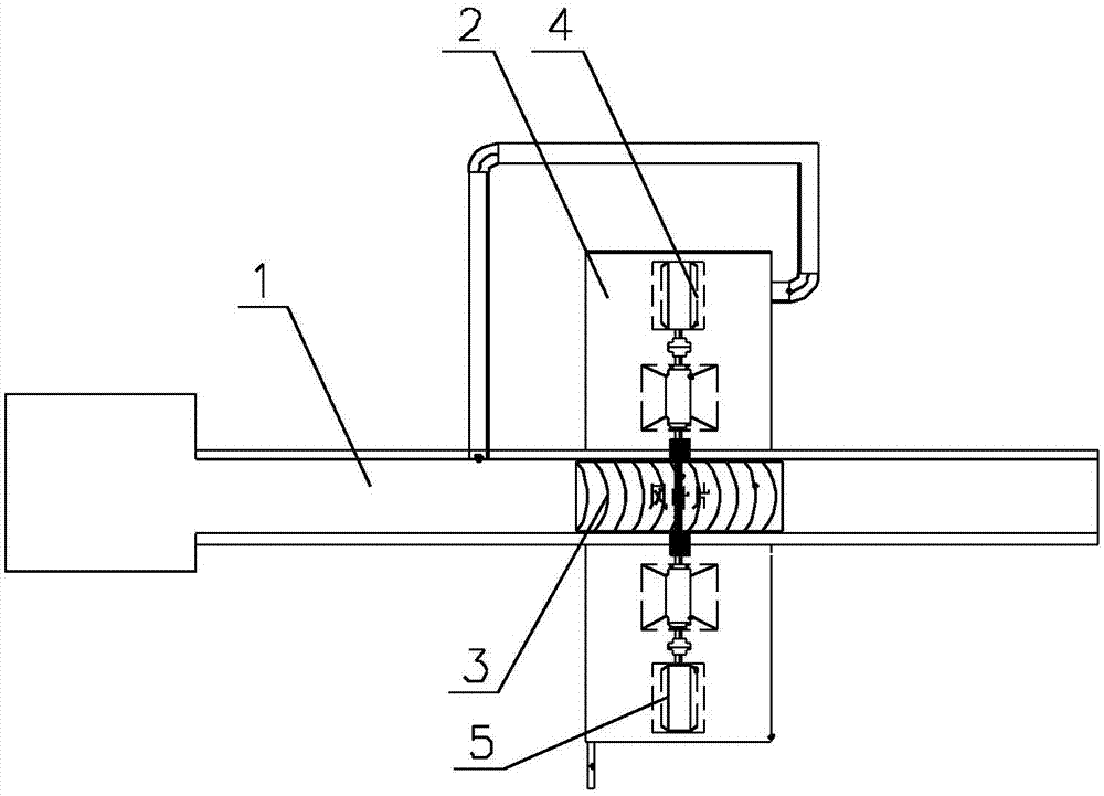
[0012] Such as figure 1 as shown, figure 1 It is a structural schematic diagram of a hot air utilization device for energy efficient utilization proposed by the present invention.

[0013] refer to figure 1 , a hot air utilization device for efficient energy utilization proposed by the present invention, comprising: a hot air channel 1, an annular energy utilization chamber 2, and a kinetic energy conversion mechanism;

[0014] The two ends of the hot air channel 1 are respectively provided with a hot air inlet and a hot air outlet. The hot air channel 1 includes a gas flow section and a gas utilization section. , the wind moving blade 3 rotates with the flow of hot air in the hot air passage 1;

[0015] The annular energy utilization chamber 2 is sleeved outside the gas utilization section, and the side wall of the annular energy utilization chamber 2 is provided with an air inlet and an air outlet, and the gas outlet communicates with the gas inlet, and the kinetic energy...


PUM


Abstract

The invention discloses a hot air utilization device for efficient energy utilization. Hot air inlets and hot air outlets are respectively provided at both ends of the hot air passage, and wind-driven blades are arranged in the hot air passage. An annular energy utilization chamber is set outside the channel, and the kinetic energy conversion mechanism is located in the annular energy utilization chamber. The kinetic energy conversion mechanism rotates with the wind blades to heat the gas in the annular energy utilization chamber. The hot air utilization device with efficient energy utilization through the above optimized design has an optimized and reasonable structural design. By setting a ring-shaped energy utilization chamber outside the hot air channel, on the one hand, the kinetic energy conversion mechanism frictionally heats the gas inside by rotating and doing work, and on the other hand On the one hand, the annular energy utilization chamber insulates the hot air passage, and the heat dissipated in the hot air passage can exchange heat with the gas in the annular energy utilization chamber, further improving the recycling rate of hot air.

Description

technical field [0001] The invention relates to the technical field of hot air utilization, in particular to a hot air utilization device for efficient energy utilization. Background technique [0002] In the fields of industrial production, waste disposal, etc., a large amount of exhaust gas is usually generated during the production or treatment process. These exhaust gases carry dust particles and harmful gases, but also carry a large amount of heat. Due to the existence of heat, no induced draft fan is required during the exhaust gas removal process. , can be efficiently eliminated with the help of its own kinetic energy. However, in the removal process, pollutant pretreatment is required, and the heat utilization rate contained in it is low. Contents of the invention [0003] In order to solve the technical problems in the background technology, the present invention proposes a hot air utilization device with high energy utilization. [0004] A hot air utilization d...

Claims


Application Information

Patent Timeline
Patent Type & Authority Applications(China)
IPC IPC(8): F24H3/00F24V40/00F01D15/00
CPCF24H3/00F01D15/00
Inventor 李启仁曹文波张文锐唐武才舒志强
Owner SINOBIOWAY DINGHE ENVIRONMENTAL PROTECTION CO LTD
Learn More