
Lap machine

A technology of a rolling machine and a winding mechanism, which is used in textiles and paper making, etc., can solve the problems of inability to solve the cleaning problem of the suction device, the influence of suction force, and the inability to work, so as to maintain the stability of the equipment, prevent blockage, and improve work. The effect of efficiency

Pending Publication Date: 2018-04-27
ZHEJIANG BOTAI TEXTILE CO LTD
View PDF10 Cites 1 Cited by
  • Summary
  • Abstract
  • Description
  • Claims
  • Application Information

AI Technical Summary

Problems solved by technology

Among them, the suction device is polluted by yarn waste due to long-term work, the suction force is greatly affected, and it may even fail to work. Therefore, the cleaning of the suction device needs to be paid attention to.
The Chinese patent No. CN200580030344 discloses a yarn splicing device, which can realize yarn joining, but cannot solve the cleaning problem of the suction device

Method used

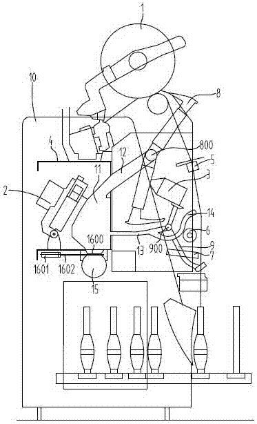
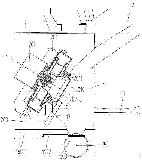

Image

  • Lap machine
  • Lap machine
  • Lap machine

Examples


Embodiment Construction

[0012] The present invention will be further described below in conjunction with accompanying drawing.

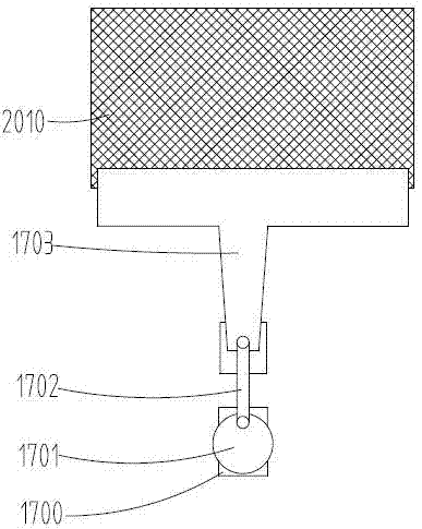
[0013] like figure 1 , 2 As shown, a coiling machine includes a frame 10 on which a winding mechanism 1, a suction device 2, a joint device 3, an auxiliary support 4, a yarn clearer 5, a tension wheel 6, a thread trimmer Device 7, first suction nozzle 8 and second suction nozzle 9. Wherein, the winding mechanism 1 is arranged at the front upper end of the frame 10 , the auxiliary bracket 4 is arranged at the rear side of the frame 10 , and the suction device 2 is arranged in the auxiliary bracket 4 .

[0014] The suction device 2 includes a mating connection base 200, a housing 201, a filter 202, a bladeless fan 203 and a first motor 204, the connection base 200 is fixedly connected to the auxiliary bracket 4, the housing 201 has a communication The suction port 2010 and the air duct 2011, the housing 201 is hinged with the connecting seat 200, the bladeless fan 203 is a...


PUM


Abstract

The invention discloses a lap machine. The lap machine comprises a rack, and a winding mechanism, a suction device, a connecting device, an auxiliary support, a yarn cleaner, a first suction nozzle and a second suction nozzle are arranged on the rack; the suction device comprises a connecting base, a shell, a filter, a bladeless fan and a first motor which are connected in a matched mode; the shell is provided with a suction inlet and an air duct which are communicated, the shell is hinged to the connecting base, and a collecting chamber communicated with the suction device is arranged in theauxiliary support; an air suction port is formed in the collecting chamber, and the air suction port is matched with a suction inlet of the suction device; the collecting chamber is further communicated with the first suction nozzle through a first pipeline arranged between the collecting chamber and the first suction nozzle, and is communicated with the second suction nozzle through a second pipeline between the collecting chamber and the second suction nozzle; the second pipeline is connected with a third suction nozzle in a matched mode. Compared with the prior art, yarn waste sucked by thesuction device can be effectively removed, blockage is prevented, working faults are avoided, and the lap machine is very beneficial to improving the working efficiency and stabilizing maintenance equipment.

Description

technical field [0001] The invention belongs to the technical field of spinning equipment, and in particular relates to a lapping machine. Background technique [0002] In the textile machine industry, the lap machine is already a mature technology. The winding machine includes multiple winding mechanisms. In the winding mechanism, after the yarn is broken, the yarn ends at the upper and lower ends need to be joined together. suction device. Among them, the suction device is polluted by yarn waste due to long-term work, and the suction force is greatly affected, and it may even fail to work. Therefore, the cleaning of the suction device needs to be paid attention to. The Chinese patent No. CN200580030344 discloses a yarn splicing device, which can realize yarn joining, but cannot solve the cleaning problem of the suction device. Contents of the invention [0003] In order to make up for the deficiencies of the prior art, the present invention provides a technical propos...

Claims


Application Information

Patent Timeline
Patent Type & Authority Applications(China)
IPC IPC(8): D01H11/00
CPCD01H11/005
Inventor 石勇陈金铨
Owner ZHEJIANG BOTAI TEXTILE CO LTD
Learn More