
Charging circuit with high-voltage fast charging and charging method thereof

A fast charging and charging circuit technology, applied in battery circuit devices, circuit devices, safety/protection circuits, etc., can solve problems such as high heat, large volume, and high cost pressure, and achieve low heat generation, high charging efficiency, and simple structure Effect

Pending Publication Date: 2018-04-24
SHENZHEN WISEPOWER INNOVATION TECH
View PDF0 Cites 3 Cited by
  • Summary
  • Abstract
  • Description
  • Claims
  • Application Information

AI Technical Summary

Problems solved by technology

The current fast charging technology is divided into low-voltage fast charging technology and high-voltage fast charging technology; low-voltage fast charging technology is a direct charging technology, excessive current will cause a large amount of line loss on the charging line, and the requirements for the charging line and the charging head are relatively high. High, high safety risk, high cost pressure; high-voltage fast charging technology adopts ordinary DC-DC step-down charging technology with inductance, adopts two sets of DC-DC charging in parallel, the charging efficiency is the same as that of ordinary charging, and cannot solve the serious problem of heat generation problem, can not increase the charging power
At the same time, the traditional charging technology must be equipped with inductive components. First, the inductive components are large in size, which will affect the space of the product. Second, when the inductive components are used, they will generate high heat, which requires the product to have heat dissipation. Space, while the price of inductive components has remained high

Method used


Image

  • Charging circuit with high-voltage fast charging and charging method thereof
  • Charging circuit with high-voltage fast charging and charging method thereof
  • Charging circuit with high-voltage fast charging and charging method thereof

Examples


Embodiment Construction

[0019] The present invention will be described in further detail below in conjunction with the embodiments and with reference to the accompanying drawings.

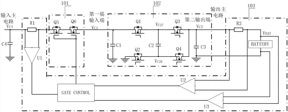
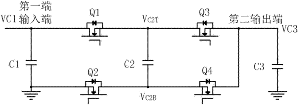
[0020] A kind of charging circuit of high-voltage fast charging of the present embodiment, refer to figure 1 , including a switch module 101, a step-down module 102 and a feedback module 103; the feedback module 103 includes a first detection resistor R1 connected to the input main circuit, a second detection resistor R2 connected to the output main circuit and charged by the output main circuit A rechargeable battery, the first detection resistor R1, the second detection resistor R2 and the two terminals of the rechargeable battery are respectively connected in parallel with the input terminals of the first comparator U1, the second comparator U2 and the third comparator U3, the first The output terminals of the comparator U1, the second comparator U2 and the third comparator U3 respectively transmit output information t...


PUM


Abstract

The invention discloses a charging circuit with high-voltage fast charging. The charging circuit comprises a switch module, a step-down module and a feedback module. The feedback module comprises a first detection resistor connected to an input main circuit, a second detection resistor connected to an output main circuit, and a rechargeable battery charged by the output main circuit. Input ends ofa first signal acquisition circuit, a second signal acquisition circuit and a third signal acquisition circuit are connected in parallel between two ends of the first detection resistor, the second detection resistor and the rechargeable battery. Output ends of the first signal acquisition circuit, the second signal acquisition circuit and the third signal acquisition circuit transmits output information to a control circuit. The switch module is connected between the step-down module and the input main circuit, and the switching state of the switch module is controlled by the control circuit. The invention also discloses a charging method of the circuit. The charging circuit has the advantages of a simple structure, no need for an inductor, high charging efficiency and low heat generation.

Description

technical field [0001] The invention relates to a power supply circuit, in particular to a high-voltage fast charging charging circuit with simple structure, no need for inductance, high charging efficiency and low heat generation and a charging method thereof. Background technique [0002] With the development of battery technology, the charging current allowed to enter the battery reaches 1.5C-2C, and a larger battery charging current is required. The current fast charging technology is divided into low-voltage fast charging technology and high-voltage fast charging technology; low-voltage fast charging technology is a direct charging technology, excessive current will cause a large amount of line loss on the charging line, and the requirements for the charging line and the charging head are relatively high. High, high safety risk, high cost pressure; high-voltage fast charging technology adopts ordinary DC-DC step-down charging technology with inductance, adopts two sets ...

Claims


Application Information

Patent Timeline
Patent Type & Authority Applications(China)
IPC IPC(8): H02J7/00
CPCH02J7/0077H02J7/0086H02J7/0034Y02E60/10
Inventor 李昊
Owner SHENZHEN WISEPOWER INNOVATION TECH
Learn More