Reflector

A reflective mirror and reflective surface technology, which is applied in the field of light source systems, can solve the problems of high positioning requirements for assembly lighting systems and light source systems, long processing cycles, and low production efficiency, and achieve good light concentration, low processing costs, and flexible use. Effect

Pending Publication Date: 2018-04-24
SHANGHAI WUJING OPTOELECTRONICS SCIANDTECH CO LTD
View PDF3 Cites 0 Cited by
  • Summary
  • Abstract
  • Description
  • Claims
  • Application Information

AI Technical Summary

Problems solved by technology

[0005] There is an obvious defect in the reflector systems of other technologies in the above-mentioned patents: very high processing accuracy requirements, long processing cycle, complicated process, and high cost; the positioning requirements for assembling the lighting system and light source system are very high, and the production cost high; low productivity

Method used


Image

  • Reflector
  • Reflector
  • Reflector

Examples


Embodiment Construction

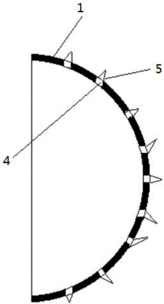
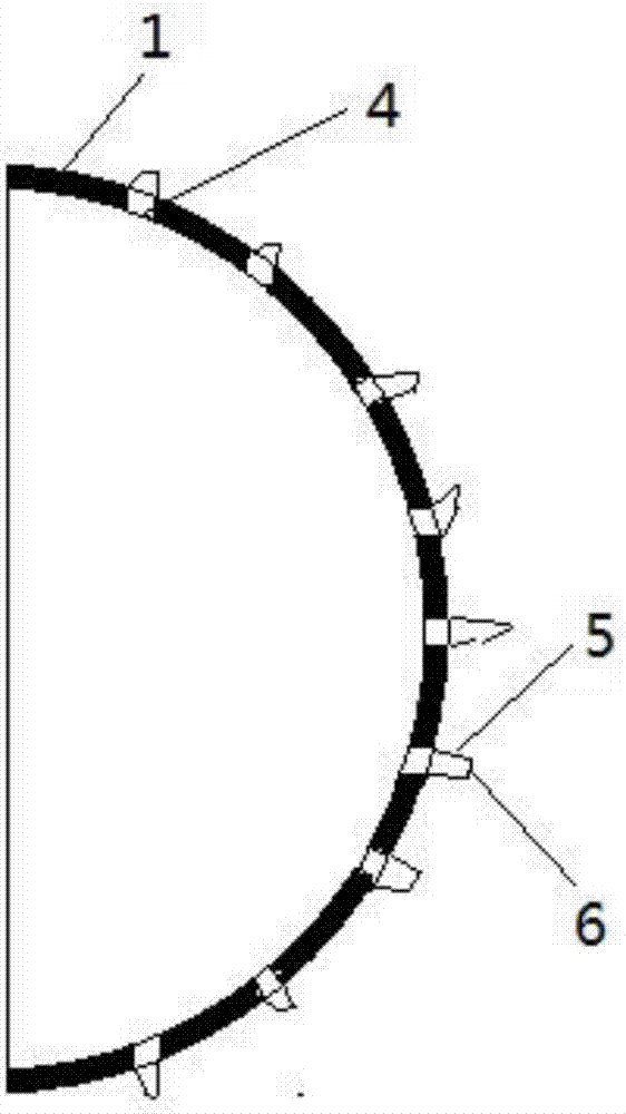
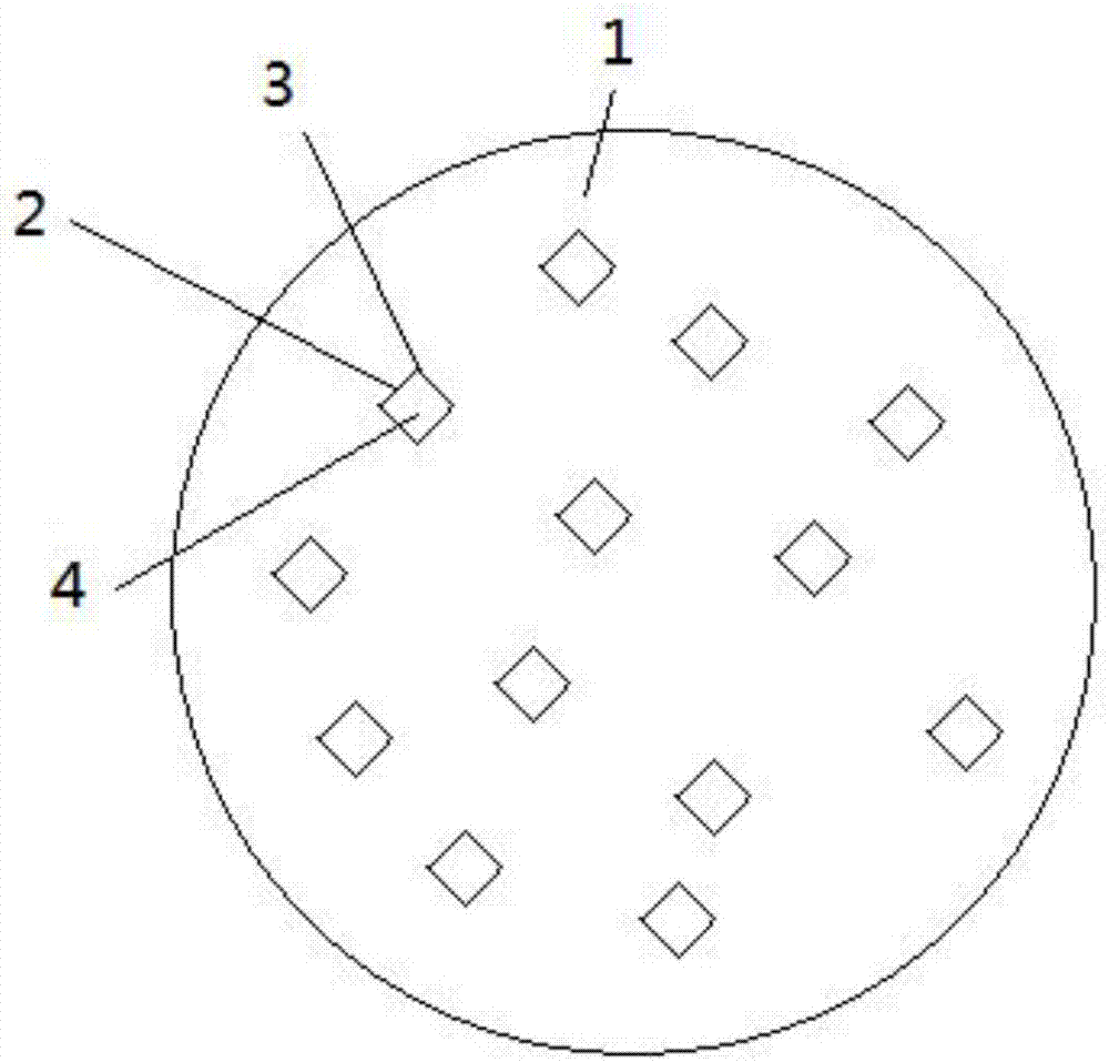
[0021] See Figure 1 ~ Figure 4 , The reflector of the present invention includes a reflecting surface 1, the reflecting surface 1 is provided with a leakage hole 4 formed by connecting a connection point 3 and a straight line 2, and the straight line 2 is provided with an outwardly extending oblique reflection Plane 5, the sides of two adjacent reflection planes 5 are connected to each other, and the ends of each reflection plane 5 are connected to each other;

[0022] The reflecting surface 1 is curved or flat;

[0023] Preferably, the angle α between two adjacent reflection planes 5 is 1 to 179°;

[0024] Preferably, the ends of each reflecting plane 5 are connected by a connecting plane 6;

[0025] Preferably, the equivalent diameter of the leak hole 4 is 0.0000000001 to 100 meters;

[0026] The term "equivalent diameter" is defined as follows. The said equivalent diameter is the sum of the lengths of individual lines divided by the circumference ratio, that is: Equivalent diamete...


PUM

PropertyMeasurementUnit
Equivalent diameteraaaaaaaaaa
Heightaaaaaaaaaa

Abstract

The invention discloses a reflector which comprises a reflecting surface, wherein a leaking hole formed by connecting a connecting point and a straight line with each other is formed in the reflectingsurface; reflecting planes extending and inclining outwards are formed in the straight line; sides of two adjacent reflecting planes are connected with each other; the ends of the reflecting planes are connected with one another. According to the reflector disclosed by the invention, the defects that electromagnetic waves cannot be emitted and utilized by light of an original spherical concave mirror along a tangent surface, as well as heat sources, infrared rays and other systems are effectively overcome, the utilization rate of the electromagnetic waves such as the light source / heat source,infrared, ultraviolet and the like is greatly improved, and the light condensing and mixing effect is 10% or more higher than that of an ordinary arc reflective concave mirror. The reflecting, condensing and mixing effect of the heat source, infrared and other electromagnetic waves is 10% or more higher than that of an ordinary arc reflective concave structure. The material and processing cost islow, the light source installation position can be set at any position on the inner side of the reflector, and the reflector is flexible and convenient to use.

Description

Technical field [0001] The invention relates to a light source system, in particular to a reflector of the light source system. Background technique [0002] At present, in the fields of optics, optoelectronics, energy, flat panel displays, and optoelectronics, the most commonly used optical devices for reflection, convergence, and homogenization of electromagnetic waves such as light or heat are concave mirrors or single-sided concave lenses or double-sided concave lenses. In commonly used flashlights, concave mirrors are used to converge and reflect light to achieve lighting effects; in CN201610073194.7, laser diodes and fluorescent materials or quantum dot materials placed at the focus of the concave mirror are used to achieve this. Laser lighting effect. [0003] In practical applications, in order to improve the effect of light reflection and convergence, methods such as plating reflective coatings and antireflection coatings are often used on the surfaces of concave mirrors ...

Claims


Application Information

Patent Timeline
IPC IPC(8): G02B5/08G02B5/09G02B5/10
CPCG02B5/0808G02B5/09G02B5/10
Inventor 赵博选石苏琴
Owner SHANGHAI WUJING OPTOELECTRONICS SCIANDTECH CO LTD
Why Eureka
Try Eureka