
A water outlet channel with flow self-balancing function

A self-balancing, water flow channel technology, applied in the direction of pipe components, mechanical equipment, pipes/pipe joints/fittings, etc., can solve problems such as uneven flow distribution, increased energy consumption of pumping stations, and obvious differences in the average speed of outflow.

Active Publication Date: 2019-08-20
YANGZHOU UNIV
View PDF7 Cites 0 Cited by
  • Summary
  • Abstract
  • Description
  • Claims
  • Application Information

AI Technical Summary

Problems solved by technology

[0002] The pump device is composed of four parts: the water inlet channel, the impeller, the guide vane body and the water outlet channel. The water flow has a large circumferential speed after the impeller rotates and does work. Although most of the circumferential kinetic energy is recovered by the guide vane body, the water flow still has A certain circumferential speed causes the water flow to enter the outlet channel in a spiral shape, resulting in a biased flow inside the outlet channel, especially for the outlet channel with a pier, the flow distribution on both sides of the pier is uneven, and the outflow The difference in the average speed is obvious, which affects the safety of the use of the outlet channel cut-off equipment, reduces the hydraulic efficiency of the outlet channel, and increases the energy consumption of the pump station. In order to solve the above problems, according to the hydraulic conditions of the outlet channel inflow, design A water outlet flow channel with flow self-balancing function

Method used


Image

  • A water outlet channel with flow self-balancing function
  • A water outlet channel with flow self-balancing function
  • A water outlet channel with flow self-balancing function

Examples


Embodiment Construction

[0019] The present invention will be further described below with reference to the accompanying drawings and the description of the drawings.

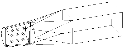
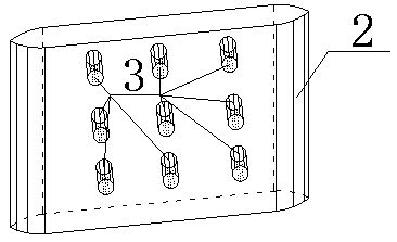
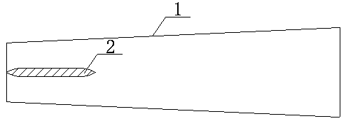
[0020] Taking a small and medium-sized pumping station as an example to illustrate, a water outlet channel 1 with flow self-balancing function is made by cast-in-place reinforced concrete vertical formwork, and the middle pier 2 is also cast in the same way when the water outlet channel vertical formwork is poured. Casting production, the artesian hole 3 is pre-buried in the middle pier 2 with PVC pipe or metal pipe, the length of the artesian hole is equal to the thickness of the middle pier, and the number of the artesian hole is set according to the length and height of the middle pier 2, Generally, it should be controlled between 9 and 12, and the top and bottom of the middle pier are consolidated with the inner wall of the outlet channel to ensure the overall stability of the outlet channel 1 and the middle pier 2.

[0021] When i...


PUM


Abstract

The patent of the present invention relates to a water outlet flow channel with flow self-balancing function, which includes two parts of the middle pier of the water outlet flow channel. ; The length of the intermediate pier is 1.5-2 times of the diameter of the inlet of the outlet channel, the thickness is 0.12-0.2 times of the inlet diameter of the outlet channel, and the height is equal to the height of the outlet channel; the starting point of the intermediate pier The position is on the inlet surface of the water outlet channel, the axis of the septum pier is parallel to the axis of the water outlet channel; the top and bottom of the septum pier are consolidated with the inner wall of the water outlet channel, and there is no protrusion on the contact surface; the self-flowing The diameter of the hole is 0.1 times the diameter of the inlet of the outlet channel, the net distance between adjacent artesian holes is 0.2 times the diameter of the inlet of the outlet channel, and the length of the artesian hole is equal to the thickness of the septum pier. The invention has a reasonable structure and is convenient to use. Through the invention, the purpose of improving the hydraulic efficiency of the water outlet channel is achieved, and the purpose of saving energy and reducing consumption is achieved.

Description

technical field [0001] The patent of the present invention relates to a water outlet channel with flow self-balancing function, which can improve the partial flow of the water outlet channel of the low-lift pump station, improve the uniformity of the velocity distribution on the outlet surface of the water outlet channel, and further recover the excess at the outlet of the guide vane. Circulation, restoring pressure energy and reducing kinetic energy belong to the technical field of pump station engineering. Background technique [0002] The pump device is composed of four parts: the water inlet channel, the impeller, the guide vane body and the water outlet channel. The water flow has a large circumferential speed after the impeller rotates to do work. A certain circumferential speed causes the water flow to enter the outlet channel in a spiral shape, resulting in a biased flow inside the outlet channel. The difference in average speed is obvious, which affects the safety ...

Claims


Application Information

Patent Timeline
Patent Type & Authority Patents(China)
IPC IPC(8): F16L55/027
Inventor 杨帆高慧刘超成立王涛周济人
Owner YANGZHOU UNIV
Learn More