Eureka AIR delivers breakthrough ideas for toughest innovation challenges, trusted by R&D personnel around the world.

Novel heat preservation solid waste fiber smashing device

A new type of waste fiber technology, applied in the application field of thermal insulation and solid waste fiber crushing equipment, can solve the problems of affecting the decomposition effect of thermal insulation and solid waste fibers, the entry of thermal insulation waste fibers into the air, and the unsatisfactory crushing effect, so as to reduce thermal insulation and solid waste. Solid waste fiber, saving working time, innovative design effect

Pending Publication Date: 2018-04-24
南京新侨鑫环保科技有限公司
View PDF0 Cites 7 Cited by
  • Summary
  • Abstract
  • Description
  • Claims
  • Application Information

AI Technical Summary

Problems solved by technology

[0003] There are many problems in the recycling process of thermal insulation solid waste fibers, and the smashing effect of some existing thermal insulation solid waste fiber crushing devices is not very satisfactory. After crushing, some large thermal insulation solid waste fibers may remain, which affects the subsequent thermal insulation solid waste The decomposition effect of waste fibers, and some crushing devices may produce more floating thermal insulation solid waste fibers during the crushing process, resulting in more floating thermal insulation solid waste fibers entering the air during collection, causing environmental pollution, and even affecting people. good health

Method used


Image

  • Novel heat preservation solid waste fiber smashing device
  • Novel heat preservation solid waste fiber smashing device

Examples


Embodiment Construction

[0016] The following will clearly and completely describe the technical solutions in the embodiments of the present invention with reference to the accompanying drawings in the embodiments of the present invention. Obviously, the described embodiments are only some, not all, embodiments of the present invention. Based on the embodiments of the present invention, all other embodiments obtained by persons of ordinary skill in the art without making creative efforts belong to the protection scope of the present invention.

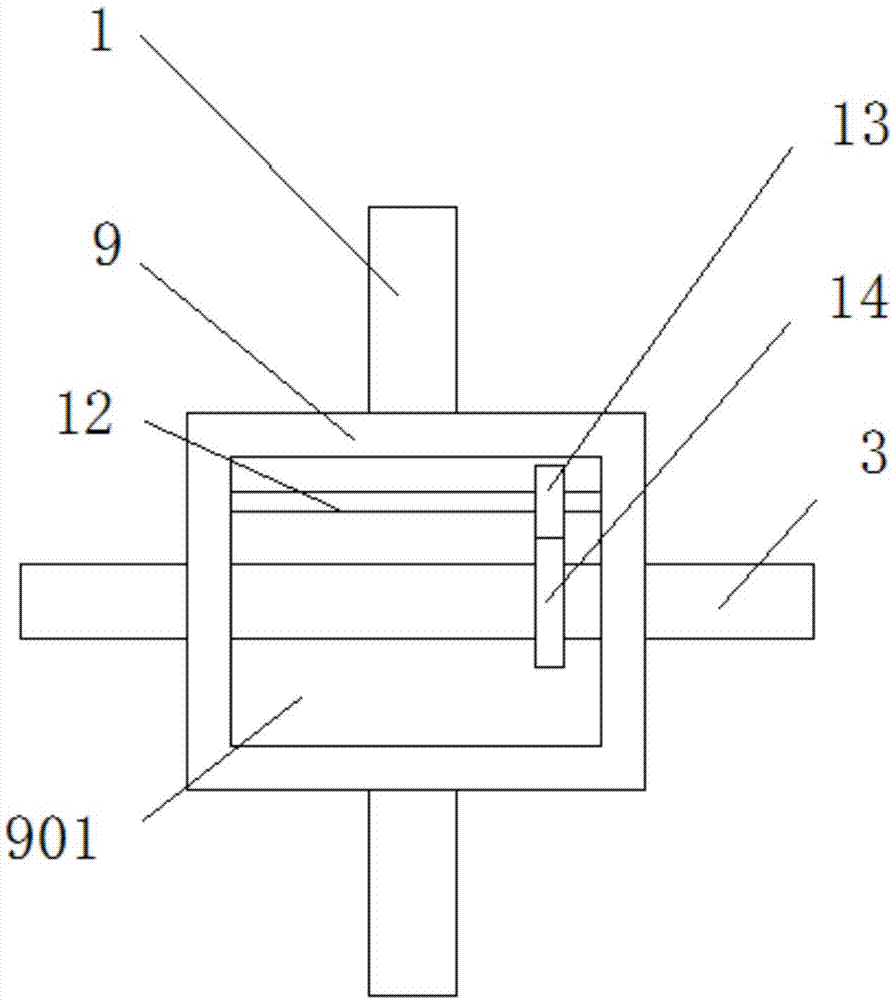
[0017] see Figure 1-2 As shown, a new thermal insulation solid waste fiber crushing device includes a main casing 1 and a support leg 2 fixedly connected to the bottom of the main casing 1, and the inside of the main casing 1 is rotatably connected with a rotating shaft 3 for easy rotation; One end of the rotating shaft 3 is rotationally connected with the first transmission wheel 4, and the first transmission wheel 4 is connected to the second transmission w...


PUM


Abstract

The invention discloses a novel heat preservation solid waste fiber smashing device. The device comprises a main shell, supporting legs, a rotating shaft, a first transmission wheel, a transmission belt, a second transmission wheel, a motor, a motor rotating shaft, a rotating cylinder, a rotating inner cavity, a first smashing knife, a second smashing knife, a fixing shaft, a first gear, a secondgear, a sieve plate, sieve plate holes, a vibrator, a discharging shell, supporting columns, a water storage tank, a submersible pump, a water outlet pipe, water mist spray heads, a heat preservationsolid waste fiber feeding port and a heat preservation solid waste fiber discharging port. According to the heat preservation solid waste fiber smashing device, the smashing knives with opposite working rotating direction are arranged, so that the smashing efficiency of the smashing device is improved, and the working time is saved; and the discharging shell is arranged, and the water mist spray heads are fixedly connected to the side wall of the discharging shell, so that the screened and floated heat preservation solid waste fiber is effectively combined with the water, then the floated heatpreservation solid waste fibers are reduced, a large amount of the heat preservation solid waste fibers are prevented from floating in the air in the discharging process, so that the environment is protected, and the body health of people is protected.

Description

technical field [0001] The invention relates to a crushing device, in particular to a novel thermal insulation solid waste fiber crushing device, which belongs to the application technical field of thermal insulation solid waste fiber crushing equipment. Background technique [0002] Insulation materials are generally materials with a thermal coefficient less than or equal to 0.12; insulation materials are developing rapidly, and the use of good insulation technology and materials in industry and construction can often achieve twice the result with half the effort. Every ton of mineral wool insulation products used in buildings can save one ton of oil a year. [0003] There are many problems in the recycling process of thermal insulation solid waste fibers, and the smashing effect of some existing thermal insulation solid waste fiber crushing devices is not very satisfactory. After crushing, some large thermal insulation solid waste fibers may remain, which affects the subse...

Claims


Application Information

Patent Timeline
IPC IPC(8): B02C18/14B02C18/18B02C23/16B02C23/40B01D47/06
CPCB01D47/06B02C18/14B02C18/18B02C23/16B02C23/40B02C2023/165B02C2201/06
Inventor 曹凤英
Owner 南京新侨鑫环保科技有限公司
Why Eureka
Eureka Blog
Learn More