Charge pump circuit, control method and display device

A control method and charge pump technology, applied in the direction of output power conversion devices, electrical components, static indicators, etc., can solve problems such as large load current, increased circuit area, and mismatching of drive capacity and drive capacity, and achieve drive capacity Consistent, equivalent capacitance value does not decrease, capacitive reactance does not increase the effect

Active Publication Date: 2020-04-07
CHIPONE TECH BEIJINGCO LTD
View PDF6 Cites 0 Cited by
  • Summary
  • Abstract
  • Description
  • Claims
  • Application Information

AI Technical Summary

Problems solved by technology

When the second driving voltage VGL is output, the external capacitor C2 discharges; when the first driving voltage VGH is output, the two external capacitors C1 and C2 are discharged in series, and in this state the equivalent capacitive reactance increases and the equivalent capacitance value decreases to the original half of the output first drive voltage VGH, resulting in the inability to provide a larger load current, which in turn reduces the first drive voltage VGH, and the drive capability of the first drive voltage does not match the drive capability of the second drive voltage, the first drive The driving capability of the voltage is halved on the original basis
Increasing the load current by replacing capacitors with large capacitance or increasing the number of capacitors will cause problems of increased circuit area and high production costs.

Method used


Image

  • Charge pump circuit, control method and display device
  • Charge pump circuit, control method and display device
  • Charge pump circuit, control method and display device

Examples


Embodiment Construction

[0039] Hereinafter, the present invention will be described in more detail with reference to the accompanying drawings. In the various figures, identical elements are indicated with similar reference numerals. For the sake of clarity, various parts in the drawings have not been drawn to scale. Also, some well-known parts may not be shown.

[0040] In the following, many specific details of the present invention are described, such as device structures, materials, dimensions, processing techniques and techniques, for a clearer understanding of the present invention. However, the invention may be practiced without these specific details, as will be understood by those skilled in the art.

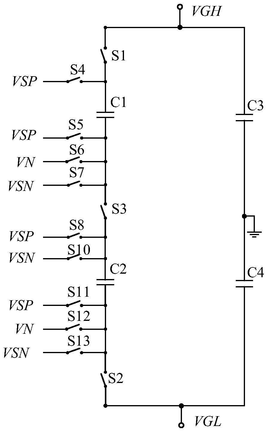
[0041] The present invention can be embodied in various forms, some examples of which are described below. According to the present invention, the first capacitor C1 can output the first driving voltage VGH or the second driving voltage VGL from the first output terminal through discharging...


PUM


Abstract

The application discloses a charge pump circuit, a control method and a display device. The charge pump circuit includes: an output terminal; at least one group of second capacitors, including a first capacitor, which outputs the first driving voltage or the second driving voltage through discharge Voltage, the second capacitor, charges the first capacitor by discharging and outputs the first driving voltage or the second driving voltage; and a switch module, used to control the output, control the charging and discharging of the second group of capacitors, and control Multiple input voltages are input to output multiple sets of first driving voltages and second driving voltages. When outputting the first driving voltage or the second driving voltage, the two external capacitors are not connected in series, the equivalent capacitance value does not decrease, and the capacitive reactance does not increase. The driving capabilities of the first driving voltage and the second driving voltage are the same. The first driving voltage and the second driving voltage are output to the driving circuit, and the driving circuit outputs the image signal to the display panel to complete image display.

Description

technical field [0001] The present invention relates to a circuit for supplying a driving voltage to a driving circuit of a liquid crystal display device, and more particularly relates to a charge pump circuit, a control method and a display device. Background technique [0002] Charge pump circuits eliminate magnetic fields and electromagnetic interference from inductors and transformers, and are frequently used as power supply circuits to supply voltage to loads. [0003] Such as figure 1 , shows a schematic diagram of a charge pump circuit for inputting a driving voltage to a driving circuit of a liquid crystal display device in the prior art. The charge pump circuit includes multiple switches, internal capacitors, multiple input voltages, and two external capacitors, such as flying capacitors. The plurality of switches are used to output multiple sets of first driving voltage VGH and second driving voltage VGL through the first output terminal and the second output ter...

Claims


Application Information

Patent Timeline
Patent Type & Authority Patents(China)
IPC IPC(8): H02M3/07G09G3/36
CPCG09G3/3696H02M3/07H02M1/009
Inventor 劉炳麟
Owner CHIPONE TECH BEIJINGCO LTD
Why Eureka
Try Eureka