Experiment table based on controllable catalytic combustion for reducing fuel tank combustibility
A catalytic combustion, test-bed technology, applied in non-electric variable control, control/regulation systems, and simultaneous control of multiple variables, etc., can solve the problems of fuel tank exhaust pollution, short life cycle, poor economy, etc., to ensure experimental The effect of safety, high degree of integration and convenient operation
- Summary
- Abstract
- Description
- Claims
- Application Information
AI Technical Summary
Problems solved by technology
Method used
Image
Examples
Embodiment 1
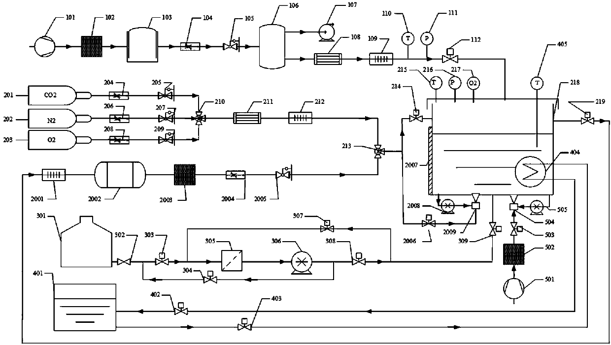
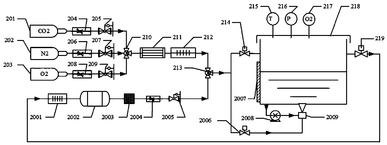
[0038] Such as figure 1 as shown, figure 1 It is a schematic diagram of the experimental platform for reducing the flammability of the fuel tank based on the controllable catalytic combustion of the present invention, the inert gas inerting subsystem, the flight environment simulation subsystem, the fuel filling and suction subsystem, the fuel heating and cooling subsystem, and the fuel pre-washing subsystem , a monitoring control subsystem; the monitoring and control subsystem controls the operation of the inert gas inerting subsystem, the flight environment simulation subsystem, the fuel filling and suction subsystem, the fuel heating and cooling subsystem, and the fuel pre-washing subsystem. Among them, the inert gas inerting subsystem is used to generate mixed inert gas for fuel tank flushing and washing inerting experiments, the flight environment simulation subsystem is used to simulate the temperature and pressure of the aircraft flight environment, etc., and the fuel f...
Embodiment 2
[0041] Such as image 3 as shown, image 3 For the flight environment simulation subsystem of the present invention, the air passes through the first air compressor 101, the first filter drier 102, the air storage tank 103, the air flow regulating valve 104, the air pressure regulating valve 105, the vacuum tank 106, the first Refrigerator 108, the first heater 109, the first temperature sensor 110, the first pressure sensor 111, the first air adjustable valve 112 to simulate the real flight environment of the aircraft, the vacuum pump 107 is used to suck the air in the vacuum tank 106, so that It generates a low-pressure environment, the first refrigerator 108 and the first heater 109 are used to generate air with different ambient temperatures, and finally the simulated ambient air enters the gas phase space of the oil tank 218 .
Embodiment 3
[0043] Such as Figure 4 as shown, Figure 4 It is the fuel filling and pumping subsystem of the present invention, which fills and sucks fuel into the fuel tank 218 according to the indication of the liquid level gauge 2007 during operation, so as to simulate the inerting performance under different fuel loading ratios. When fuel is added to the fuel tank 218, the second fuel flow adjustable valve 304 and the third fuel flow adjustable valve 307 are closed, and the fuel flows through the oil storage tank 301, the gate valve 302, the first fuel flow adjustable valve 303, and the fuel oil in sequence. The filter 305, the second fuel pump 306, the fourth fuel flow adjustable valve 308, and the fifth fuel flow adjustable valve 309 reach the fuel tank 218; when the fuel in the fuel tank is sucked, the first fuel flow adjustable valve 303 and the fourth fuel flow are closed. The adjustable fuel flow valve 308 opens the second adjustable fuel flow valve 304 and the third adjustable...
PUM
 Abstract
Description
Claims
Application Information
 - Generate Ideas
- Intellectual Property
- Life Sciences
- Materials
- Tech Scout
- Unparalleled Data Quality
- Higher Quality Content
- 60% Fewer Hallucinations
Browse by: Latest US Patents, China's latest patents, Technical Efficacy Thesaurus, Application Domain, Technology Topic, Popular Technical Reports.
© 2025 PatSnap. All rights reserved.Legal|Privacy policy|Modern Slavery Act Transparency Statement|Sitemap|About US| Contact US: help@patsnap.com


