
Unidirectional shearing model case for vibration table tests

A shear model box and shaking table test technology, which is applied in the field of civil engineering, can solve problems such as less consideration of the influence of lateral earth pressure, shedding of adjacent frames, and the existence of boundary effects, so as to avoid vibration interference, reduce errors, and reduce impacts Effect

Pending Publication Date: 2018-04-20
DALIAN UNIV OF TECH
View PDF0 Cites 5 Cited by
  • Summary
  • Abstract
  • Description
  • Claims
  • Application Information

AI Technical Summary

Problems solved by technology

The free sliding between adjacent layers of the shear model box can simulate the shear deformation of the soil during the vibration process, so the shear model box is currently widely used, but due to the difference between the material density of the model box and the experimental soil density, There is a boundary effect in the vibration process, and only the middle part of the experimental soil can reflect the vibration response of the soil
[0003] The current shear model box is in the form of a layered frame. During the vibration process, there is a danger of falling off due to excessive displacement of the adjacent frame. At the same time, the layered frame will generate a certain inertia force during the vibration process. On the soil, the vibration interference of the model box to the foundation soil cannot be avoided, which makes the stress state of the experimental soil different from the stress state of the real soil.
[0004] Under the action of earthquake load, the vibration of the soil is affected by the lateral earth pressure of the surrounding soil, and the current model box rarely considers the influence of the lateral earth pressure on the experimental soil

Method used


Image

  • Unidirectional shearing model case for vibration table tests
  • Unidirectional shearing model case for vibration table tests
  • Unidirectional shearing model case for vibration table tests

Examples


Embodiment Construction

[0019] The specific embodiments of the present invention will be described in detail below in conjunction with the technical solutions and accompanying drawings.

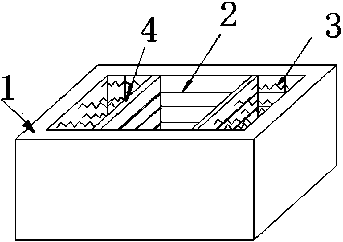
[0020] A kind of unidirectional shear model box used for shaking table test, the peripheral box 1 is used as the peripheral structure, and there are several longitudinal chute 2 on the inside of the longitudinal plate of the peripheral box 1, as the movement of the layered side plate 4 guide.

[0021] The structure of longitudinal chute 2 is as follows image 3 As shown, the two ends of the layered side plate 4 are embedded in the longitudinal chute 2, and the bead row is embedded between the end and the peripheral box 1, so that the layered side plate 4 can slide freely in the longitudinal chute 2, reducing the impact of the model box on the soil. interference and impact.

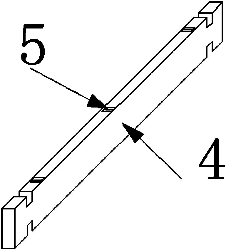
[0022] The layered side panels 4 in the box have a structure such as figure 2 As shown, the two ends are T-shaped, and there must be a cert...


PUM


Abstract

The invention belongs to the field of civil engineering, and relates to a unidirectional shearing model case for vibration table tests. The model case mainly consists of a peripheral case body, layering side plates and springs, wherein the two ends of the layering side plates are embedded in longitudinal slide grooves formed in the model case body; a plate gap slide groove is formed between the upper and lower adjacent layering side plates; roll balls are arranged in the plate gap slide groove; the inner side of each layering side plate and the peripheral case body are connected by the springs. Through the springs, a test soil body has certain lateral pressure in the vibration process, so that the lateral soil pressure in the soil body vibration process is simulated; the layering side plates can freely slide in the longitudinal slide grooves; the influence of friction on the test soil body is reduced, so that the tests can effectively simulate the vibration mechanical property of the soil body. The unidirectional shearing model case has the advantages that the safety is realized; the structure is simple; the application is convenient.

Description

technical field [0001] The invention belongs to the field of civil engineering and relates to a unidirectional shear model box used for shaking table tests. Background technique [0002] Under the action of an earthquake, the soil is subjected to dynamic loads, and the state of the soil will change, which will lead to the occurrence of geological disasters. The transmission of seismic waves makes the soil vibrate in multiple directions, and the shallow surface is mainly shear deformation, so the shaking table test generally simulates the shear deformation of soil. The shaking table test is an important means to study the seismic response. The model box can transmit the vibration to the experimental soil to simulate the interaction of the earthquake with the experimental object, so that it can reflect the response of the soil under the vibration to a certain extent. Existing shaking table model boxes generally include rigid model boxes, cylindrical flexible model boxes and s...

Claims


Application Information

Patent Timeline
Patent Type & Authority Applications(China)
IPC IPC(8): G01M7/04
CPCG01M7/04
Inventor 赵维王润清王忠涛宋晓龙宋怀博
Owner DALIAN UNIV OF TECH
Learn More