Wear-resistant multi-stage pressure reduction mechanism and application method thereof

A one-piece, inner-tube technology, applied to mechanical equipment, engine components, safety valves, etc., can solve problems such as large safety hazards, high cost, and easy wear, and achieve the effects of alleviating wear, reducing medium flow rate, and extending the operating cycle

Pending Publication Date: 2018-04-20
SHANGHAI HOTO PETROCHEM ENG +1
View PDF8 Cites 1 Cited by
  • Summary
  • Abstract
  • Description
  • Claims
  • Application Information

AI Technical Summary

Problems solved by technology

[0004] Aiming at the aforementioned technical problems of the pressure reducing valve device used in the processing of residual oil, such as easy wear of the valve, great potential safety hazards, and high cost, the embodiment of the present invention provides an anti-wear multi-stage pressure reducing mechanism and its application method, which is suitable for For the high temperature and high pressure working conditions of residual oil processing, the use of the anti-wear multi-stage pressure reducing mechanism can effectively improve the working condition of the pressure reducing valve, prolong the service life of the equipment and the operation cycle of the device

Method used


Image

  • Wear-resistant multi-stage pressure reduction mechanism and application method thereof

Examples


Embodiment Construction

[0020] In order to make the technical problems, technical solutions and advantages to be solved by the present invention clearer, the following will describe in detail with reference to the drawings and specific embodiments.

[0021] Aiming at the existing problems, the present invention provides an anti-wear multi-stage decompression mechanism and its application method. The anti-wear multi-stage decompression mechanism is especially suitable for use under high pressure drop and high wear conditions, and can effectively improve decompression valve working conditions, prolonging the service life of the equipment and the operating cycle of the device.

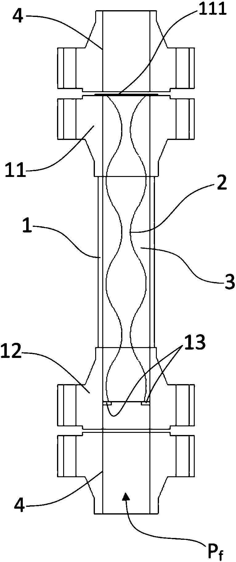
[0022] The anti-wear multi-stage pressure-reducing mechanism of this embodiment is as follows: figure 1 As shown, it includes a hollow inner cylinder 2 and an outer cylinder 1 sleeved outside the inner cylinder. There is a cavity 3 between the outer cylinder 1 and the inner cylinder 2; For the first connection part 11 and the s...


PUM


Abstract

An embodiment of the invention provides a wear-resistant multi-stage pressure reduction mechanism. The wear-resistant multi-stage pressure reduction mechanism comprises an outer cylinder and an innercylinder, wherein the outer cylinder and the inner cylinder are connected in a sleeving mode, and a cavity is formed between the inner cylinder and the outer cylinder. A first connecting portion and asecond connecting portion are installed at the upper end and the lower end of the outer cylinder correspondingly, and locating plates are arranged on the inner side of the lower end of the outer cylinder. The inner cylinder is connected between the locating plates and the first connecting portion, and the two ends of the cavity are sealed by the locating plates and the first connecting portion correspondingly. The value of the inner diameter of the inner cylinder is repeatedly changed in the axial direction. When the wear-resistant multi-stage pressure reduction mechanism is connected to a pipeline, fluid circulates on the inner side of the inner cylinder. The embodiment of the invention further provides an application method of the wear-resistant multi-stage pressure reduction mechanism.Due to the fact that the wear-resistant multi-stage pressure reduction mechanism is installed on the downstream portion of a pressure reducing valve, the operating pressure difference of the pressurereducing valve can be remarkably reduced, the remaining pressure difference of a system is borne by the wear-resistant multi-stage pressure reduction mechanism, the flow velocity of media at the position of a valve element of the pressure reducing valve is remarkably reduced, the wear of the valve element is greatly reduced, the running period of the high-grade special pressure reducing valve issubstantially prolonged, and the wear of a pipeline located behind the valve is effectively reduced.

Description

technical field [0001] The invention belongs to the technical field of residual oil processing, and in particular relates to an anti-wear multi-stage pressure-reducing mechanism. The invention also provides an application method of the anti-wear multi-stage pressure-reducing mechanism. Background technique [0002] Slurry bed / suspension bed residue hydrocracking and ebullating bed residue hydrocracking processes are new processes developed in recent years for processing heavy and low-quality residues. The process is characterized by harsh reaction conditions (high temperature, high pressure, hydrogen exposure) and The reaction product contains solid catalyst particles. The reaction product is generally separated from oil gas and oil residue in the reaction product high-pressure separator. The separated oil residue is depressurized by a high-grade special pressure reducing valve and sent to the downstream atmospheric and vacuum oil residue separation device for treatment. . ...

Claims


Application Information

Patent Timeline
Patent Type & Authority Applications(China)
IPC IPC(8): F16K17/20
CPCF16K17/20
Inventor 钟小萍扬善升张明会王铁军
Owner SHANGHAI HOTO PETROCHEM ENG
Why Eureka
Try Eureka