
Punching device and multi-station punching machine

A technology of punching device and punching knife, which is applied in leather punching/punching/cutting, metal processing, small raw leather/big raw leather/leather/fur mechanical treatment, etc., which can solve the problems of low punching efficiency and achieve improvement performance, saving energy, improving processing efficiency and the effect of qualified rate

Active Publication Date: 2018-04-20
DONGGUAN EMMA CNC TECH CO LTD
View PDF8 Cites 1 Cited by
  • Summary
  • Abstract
  • Description
  • Claims
  • Application Information

AI Technical Summary

Problems solved by technology

The present invention also provides a multi-station punching machine, the purpose of which is to combine multiple punching devices to realize multi-station operation, thereby solving the technical problem of low punching efficiency in the prior art

Method used


Image

  • Punching device and multi-station punching machine
  • Punching device and multi-station punching machine
  • Punching device and multi-station punching machine

Examples


Embodiment Construction

[0066] In order to make the object, technical solution and advantages of the present invention clearer, the present invention will be further described in detail below in conjunction with the accompanying drawings and embodiments. It should be understood that the specific embodiments described here are only used to explain the present invention, not to limit the present invention. In addition, the technical features involved in the various embodiments of the present invention described below can be combined with each other as long as they do not constitute a conflict with each other.

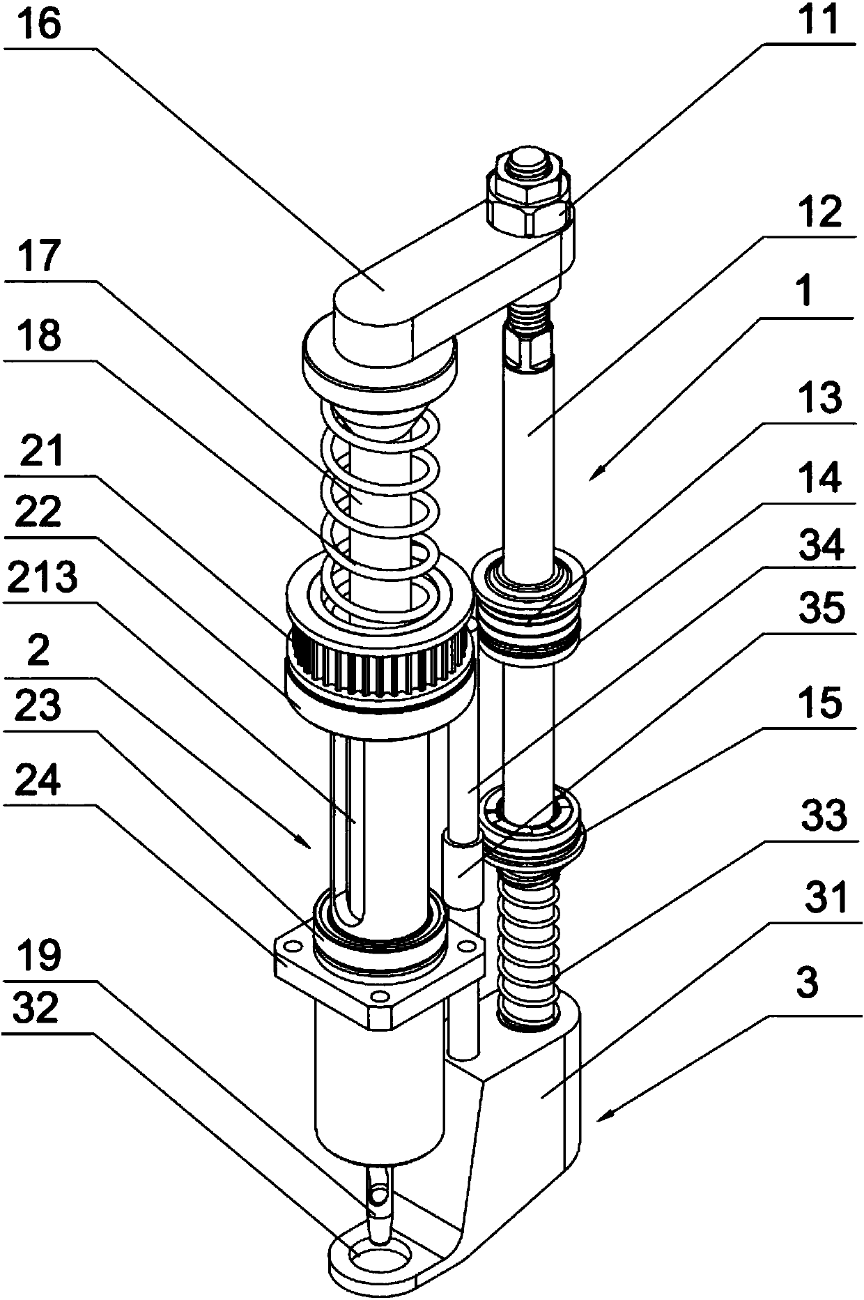
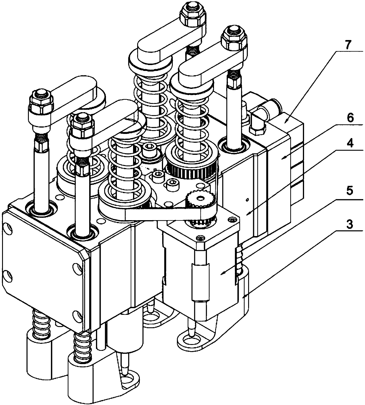
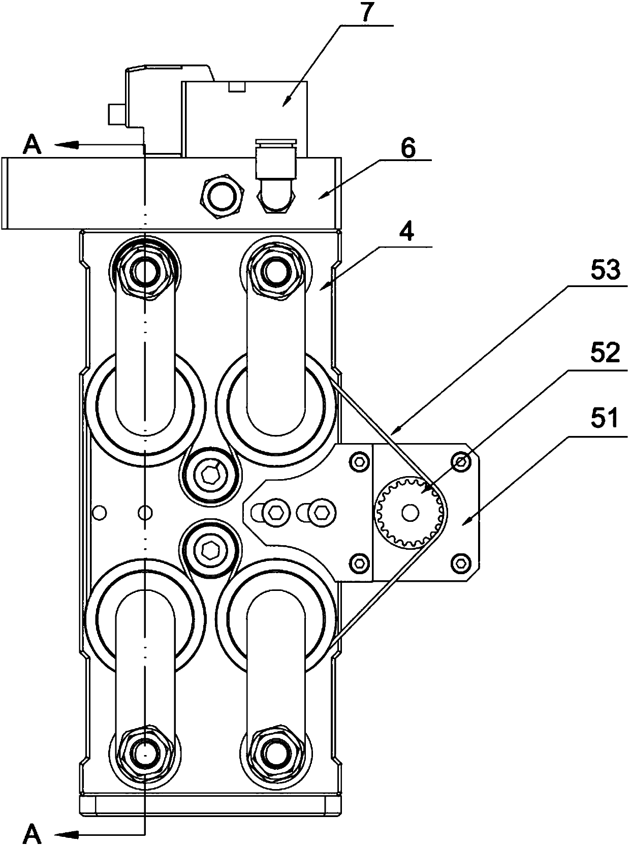
[0067] Figure 1-7 It is the first embodiment of the present invention. The first embodiment of the present invention is a punching device and a four-station punching machine composed of the punching device.

[0068] Such as Figure 1~3 , the punching device of the present invention includes a punching assembly 1, a rotating assembly 2, and a pressing assembly 3. The four-station punching mac...


PUM

PropertyMeasurementUnit
thicknessaaaaaaaaaa
thicknessaaaaaaaaaa

Abstract

The invention discloses a punching device and a multi-station punching machine and belongs to the field of processing of leather. The punching device comprises an air cylinder, a punching cutter connection rod, a punching cutter pressing plate, a rotary driving rod, a punching cutter and a driven gear, wherein the air cylinder is provided with a piston rod; the upper end and the lower end of the piston rod extend out of the air cylinder; the upper ends of the piston rod and the punching cutter connection rod are connected with the punching cutter pressing plate; the punching cutter connectionrod is capable of rotating relative to the punching cutter pressing plate; the punching cutter is mounted at the lower end of the punching cutter connection rod; the driven gear comprises gear teeth and a shaft sleeve; the gear teeth are distributed along the circumferential direction of the outer side of the shaft sleeve; the shaft sleeve sleeves the lower part of the punching cutter connection rod; at least one sliding groove is formed in the shaft sleeve along an axial direction; one end of the rotary driving rod is located in the sliding groove; the other end of the rotary driving rod is fixed on the punching cutter connection rod. When the device operates, the rotating feeding and the punching feeding of the punching cutter are carried out simultaneously, so that the punching thickness is higher; the maximum punching thickness can reach 15mm according to different materials; a plurality of punching devices are combined to form a multi-station punching machine; the multi-station simultaneous processing can be achieved; the efficiency is improved.

Description

technical field [0001] The invention belongs to the field of leather processing, and more specifically relates to a punching device and a multi-station punching machine. Background technique [0002] At present, science and technology are advancing by leaps and bounds, market competition is becoming increasingly fierce, and competition is ubiquitous in modern society. Product quality and output are fundamental to ensure that enterprises remain invincible in the fierce market competition. At present, in the production process of leather products, leather cutting machines can only punch conventional leather with a thickness of less than 3 mm, and can only punch single or double holes at a time. This kind of punching speed is slow, low in efficiency, and expensive High, and the scope of application is small, the technology is difficult to meet the requirements of customers. Contents of the invention [0003] In view of the above defects or improvement needs of the prior art,...

Claims


Application Information

Patent Timeline
Patent Type & Authority Applications(China)
IPC IPC(8): B26F1/14B26F1/04B26D5/12B26D7/02B26D7/26B26D7/00C14B5/02
CPCC14B5/02B26D5/12B26D7/0006B26D7/025B26D7/2614B26F1/04B26F1/14Y02E60/10
Inventor 王炜棠陈永君
Owner DONGGUAN EMMA CNC TECH CO LTD
Learn More