
Pressure cooker with pressure-limiting valve control structure

A technology of control structure and pressure-limiting valve, applied in the field of pressure cooker, can solve the problems such as the space occupied by the handle of the pressure cooker that cannot be compressed, and the inability to use a lift-up handle, etc.

Inactive Publication Date: 2018-04-20
浙江凯达工贸有限公司
View PDF5 Cites 64 Cited by
  • Summary
  • Abstract
  • Description
  • Claims
  • Application Information

AI Technical Summary

Problems solved by technology

[0003] The technical problem to be solved in the present invention is that the position of the pressure limiting valve of the existing pressure cooker is located in the middle of the pot cover, which makes it impossible to use the lifting handle and compress the space occupied by the handle of the pressure cooker, thereby providing a control valve with a pressure limiting valve. For the pressure cooker with the same structure, the pressure limiting valve is set on the side of the lid, and the center of the lid is left for the upper handle

Method used


Image

  • Pressure cooker with pressure-limiting valve control structure
  • Pressure cooker with pressure-limiting valve control structure
  • Pressure cooker with pressure-limiting valve control structure

Examples


Embodiment Construction

[0018] The present invention will be further described below in conjunction with the accompanying drawings and specific embodiments.

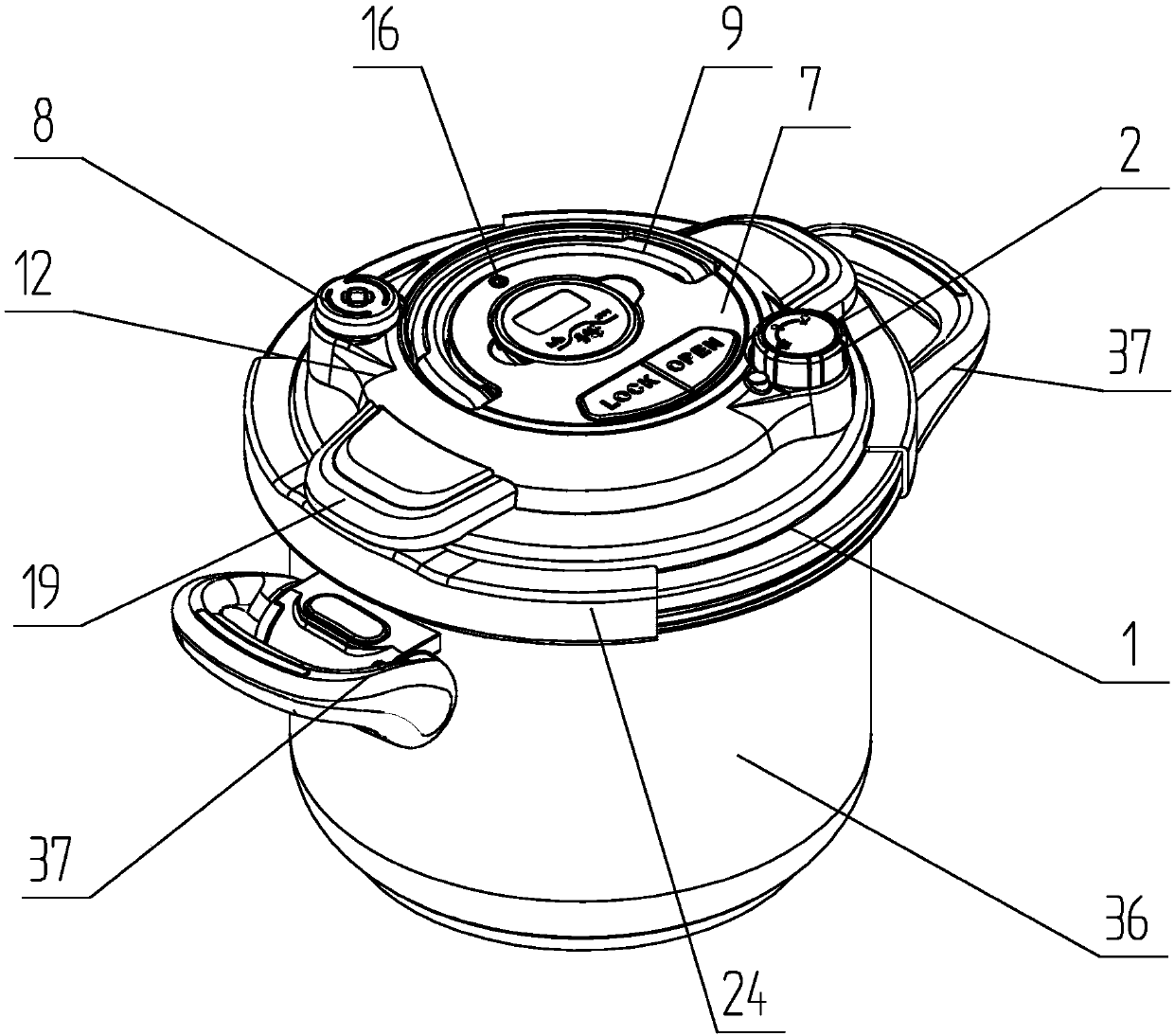
[0019] Such as figure 1 The shown embodiment is a pressure cooker with a pressure limiting valve control structure. The pressure cooker of this example comprises pot body 36 and pot lid 1. The both sides of pot body are equipped with handle 37. A pair of clamps 24 are detachably clamped between the upper edge of the pot body and the lower edge of the pot cover. The pot cover is provided with a semicircular handle 9. The pot cover is also provided with a secondary panel 12, a pressure limiting valve assembly 8 and a pressure limiting valve adjusting knob 2, the cover plate is fastened on the secondary panel, and the cover plate 7 is provided with a safety valve 16. The main panel 19 is fixed on the pot cover.

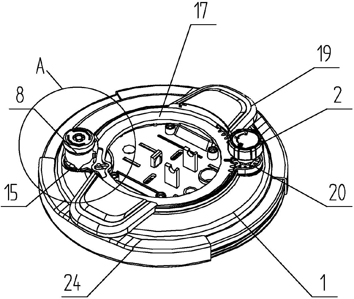
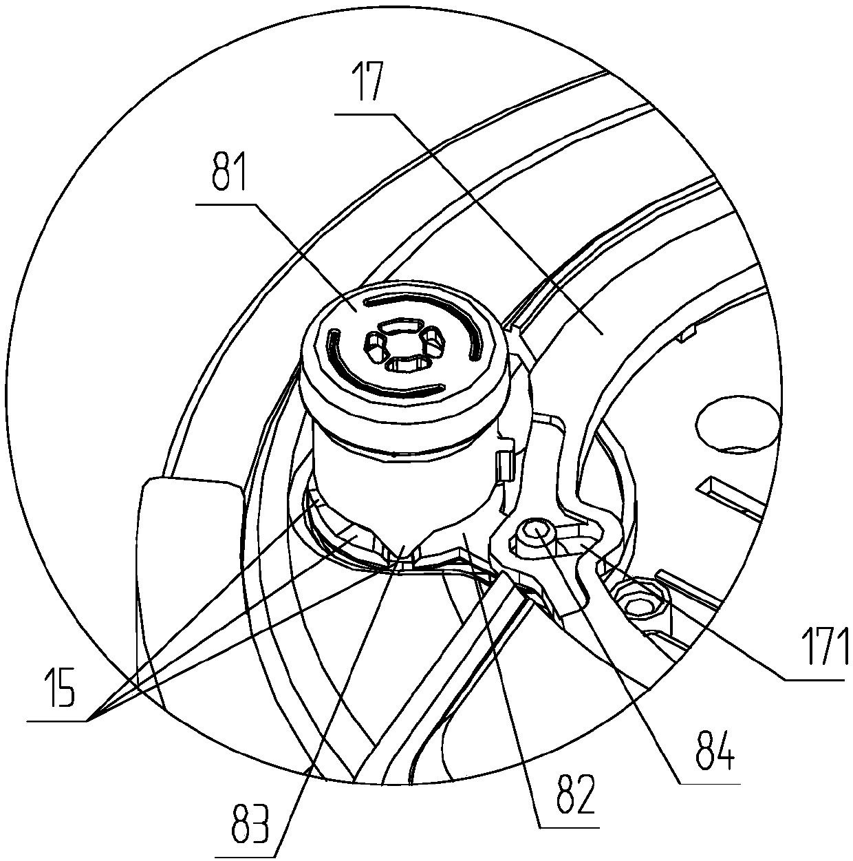
[0020] Such as figure 2 , image 3 As shown, the left side of the pot cover is provided with a pressure-limiting valve assembly ...


PUM


Abstract

The invention discloses a pressure cooker with a pressure-limiting valve control structure. The pressure cooker comprises a cover. A pressure-limiting valve component is arranged on the lateral side of the cover, and comprises an exhaust hole communicated with the cover in the thickness direction. A gravity-type pressure-limiting valve is arranged in an upper end gap of the exhaust hole in a sleeved mode, can only ascend and descend on an exhaust pipe axially and cannot rotate circumferentially. A pressure-limiting valve height adjusting step is arranged at the root of the exhaust hole rotationally in an encircling mode, and encircles the circumferential outer side of the exhaust pipe. Three pressure-limiting valve steps with different heights are arranged in the thickness direction of thecover sequentially, and the adjacent steps are in smooth transition. A step contact is arranged at the lower end of the pressure-limiting valve in a protruded mode, and can contact one of the pressure-limiting valve steps correspondingly. The pressure cooker has the advantages that the pressure-limiting valve is arranged on the lateral side of the cover, the center of the cover can be reserved for arrangement of a lifting-type handle, and the function of accurately controlling ascending and descending of the pressure-limiting valve is provided.

Description

technical field [0001] The invention belongs to the field of cooking utensils, in particular to a pressure cooker with a pressure limiting valve control structure. Background technique [0002] Chinese patent document CN204995242U disclosed "exhaust device and electric pressure cooker" on July 30, 2015. The exhaust device includes: an exhaust pipe; a pressure limiting valve, and the exhaust pipe is installed in the pressure limiting valve; a turntable, the pressure limiting valve is installed on the exhaust turntable, and the rotation of the exhaust turntable pushes the movement of the pressure limit valve; and an electromagnetic element, an electromagnetic push rod is arranged on the electromagnetic element, and the electromagnetic push rod In contact with the exhaust turntable, the electromagnetic element pushes the exhaust turntable to rotate through the electromagnetic push rod, and realizes the long-distance exhaust function through the separation of the pressure limiti...

Claims


Application Information

Patent Timeline
Patent Type & Authority Applications(China)
IPC IPC(8): A47J27/08A47J27/09
CPCA47J27/08A47J27/09
Inventor 叶广明
Owner 浙江凯达工贸有限公司
Learn More