Housing with fluid duct

A shell and channel technology, applied in the field of shells, can solve problems such as re-locking and achieve the effect of flexible assembly sequence

Active Publication Date: 2018-04-17
ROBERT BOSCH GMBH
View PDF2 Cites 1 Cited by
  • Summary
  • Abstract
  • Description
  • Claims
  • Application Information

AI Technical Summary

Problems solved by technology

However, the additional opening has to be closed again in an additional, subsequent work step

Method used


Image

  • Housing with fluid duct
  • Housing with fluid duct
  • Housing with fluid duct

Examples


Embodiment Construction

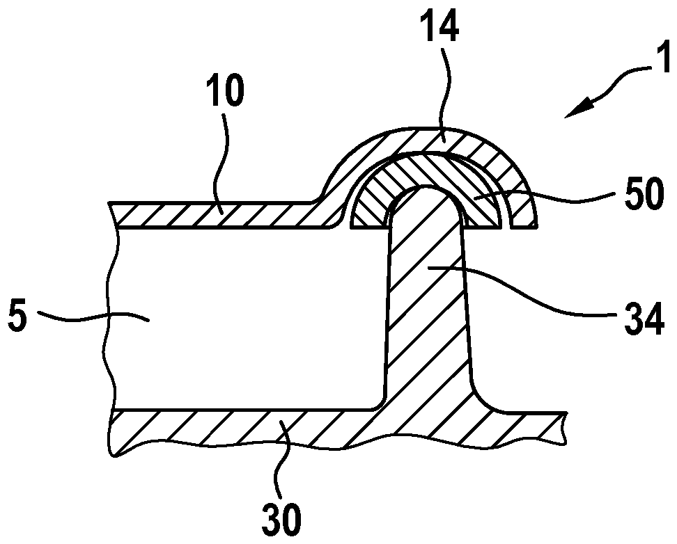
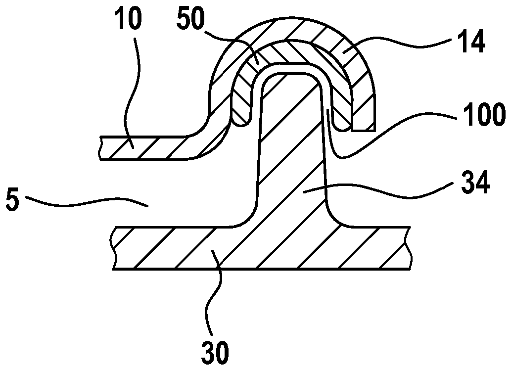
[0031] exist figure 1 A top view of the housing 1 is shown in . The housing 1 comprises a first housing element 10 and a second housing element 30 . The first housing element 10 is preferably designed as a deep-drawn part. The configuration as a deep-drawn part enables an easy and cost-effective production of the first housing element 10 . The second housing element 30 is preferably produced by means of die-casting technology, in particular as an aluminum or magnesium die-cast part. In particular, housing 1 is designed to accommodate electrical components, in particular circuit boards. In particular, the printed circuit board can form a control unit of the electric drive. Preferably, the circuit board forms an electrical control unit for a fan motor, in particular a fan motor or a pump of an HVAC system. The second housing element 30 has a cooling body whose main function is to dissipate heat generated during operation of the electrical components. The second housing ele...


PUM


Abstract

The invention relates to a housing (1), in particular for a control unit of a fan motor, having at least two housing elements (10, 30) and having a connecting element (50), wherein the housing elements (10, 30) interact with the connecting element (50), and wherein the brought-together housing elements (10, 30) form an interior region (5). According to the invention, a duct (40) is formed which, before and / or during the assembly of the housing (1), in particular before and / or during the bringing-together of the housing elements (10, 30), connects the interior region (5) and the surroundings ofthe housing (1) and permits a fluid flow between the interior region (5) and the surroundings, and which, upon the completion of the assembly process, is closed off by way of the interaction of at least one housing element (10, 30) and the connecting element (50).

Description

technical field [0001] The invention relates to a housing of the type according to the independent claim. Background technique [0002] Housings are known which consist of two housing elements and a sealing element. The sealing element is arranged between the two housing elements. The housing has an inner region in which in particular electrical components can be arranged. During assembly, the two housing elements are joined together. In this case, air is forced out of the inner region of the housing. The compressed air flows from the inner region beside the sealing element into the environment. Air flowing sideways can cause undesired compression of the sealing means. Due to the compression of the sealing means, the housing may leak in the region of the compressed sealing means. In order to counteract unintentional crushing, additional openings are provided in the housing element. However, the additional opening has to be closed again in an additional subsequent work...

Claims


Application Information

Patent Timeline
Patent Type & Authority Applications(China)
IPC IPC(8): H05K5/00H05K5/02H05K5/06
CPCH05K5/061H05K5/0052H05K5/0213F04D25/068H05K5/0017H05K5/0217
Inventor D.福尔默W.格吕克M.舍尔曼A.阿斯兰-许尔斯特L-T.施图本博德R.莱曼
Owner ROBERT BOSCH GMBH
Why Eureka
Try Eureka