
A microphone sealing device

A technology of sealing device and microphone, which is applied in the direction of microphone mouth/microphone accessories, sensors, telephone structure, etc., which can solve the problems of poor sealing reliability and achieve the effect of high sealing reliability and easy disassembly and recycling

Active Publication Date: 2020-10-16
ZTE CORP
View PDF4 Cites 0 Cited by
  • Summary
  • Abstract
  • Description
  • Claims
  • Application Information

AI Technical Summary

Problems solved by technology

[0005] The technical problem to be solved by the present invention is to provide a microphone sealing device to solve the problem of poor sealing reliability caused by the influence of manufacturing tolerances in the sealing structure of the prior art

Method used


Image

  • A microphone sealing device
  • A microphone sealing device
  • A microphone sealing device

Examples


Embodiment Construction

[0024] In order to solve the problem of poor sealing reliability of the sealing structure in the prior art due to the influence of manufacturing tolerances, the present invention provides a microphone sealing device. The present invention will be further described in detail below with reference to the accompanying drawings and embodiments. It should be understood that the specific embodiments described here are only used to explain the present invention, not to limit the present invention.

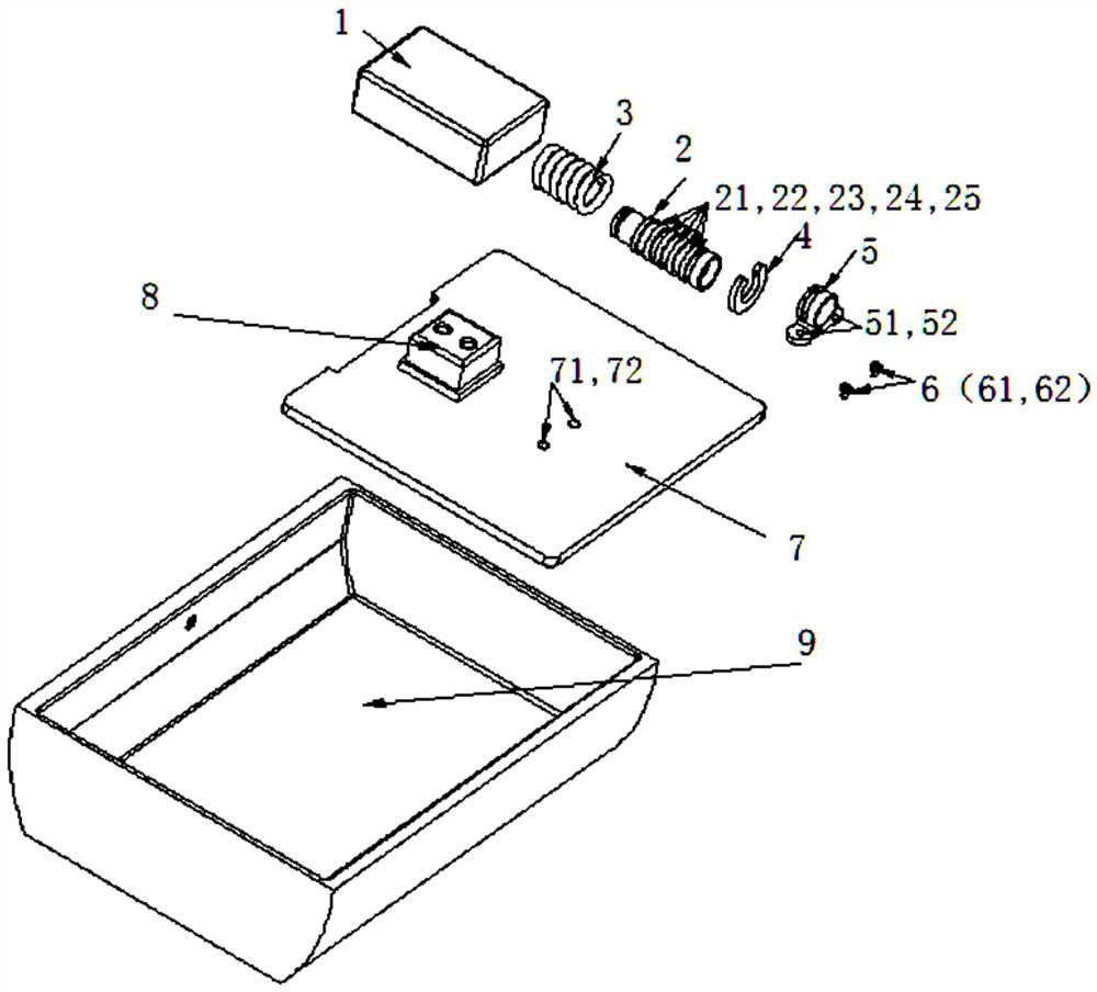
[0025] The exploded schematic diagram and cross-sectional view of a microphone sealing device according to the embodiment of the present invention are as follows: image 3 and Figure 4 As shown, the device includes a sealing sleeve, an elastic body, a pressing part and a positioning part; the microphone 8 is welded on the main board 7, the sealing sleeve is set on the microphone 8, and the elastic body abuts against the sealing sleeve and the Between the pressing parts, the pressing part...


PUM


Abstract

Disclosed is a microphone sealing device, comprising a sealing sleeve, an elastic body, a compression portion and a positioning portion, wherein the sealing sleeve is sheathed on a microphone; the elastic body abuts between the sealing sleeve and the compression portion; and the compression portion is mounted on a main board by means of the positioning portion. In an embodiment of the present invention, by compressing the elastic body by means of the compression portion, the elastic body transfers a force to the sealing sleeve, and then, the sealing sleeve pushes against a housing, thus realizing the tight press fitting of the sealing sleeve and the housing and achieving a sealing function. The above-mentioned technical solution is highly reliable in terms of sealing and is convenient to disassemble and recycle.

Description

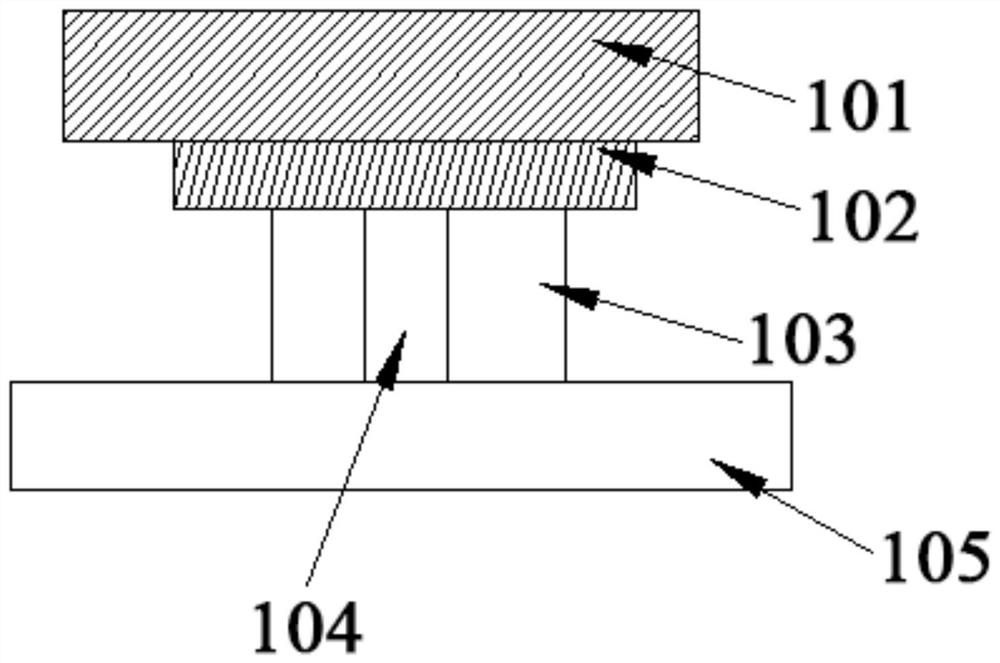
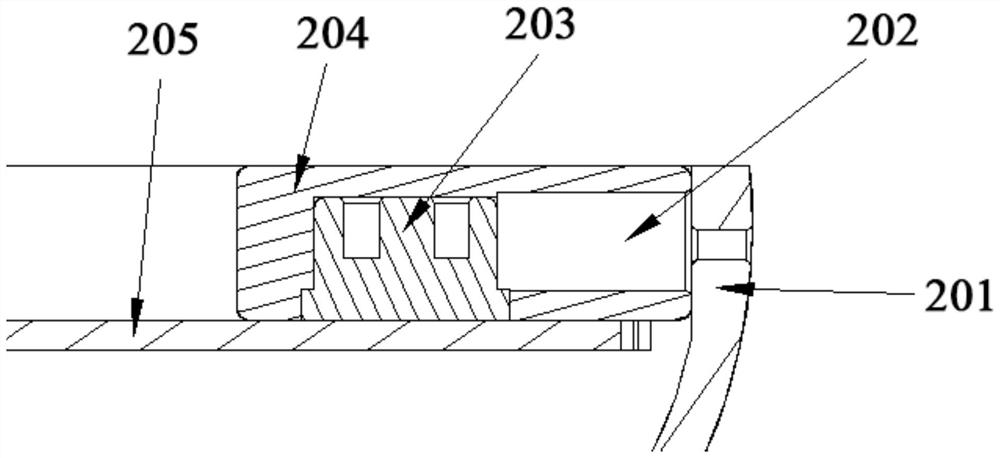
technical field [0001] The technical field of audio equipment of the present invention, in particular, relates to a microphone sealing device. Background technique [0002] MIC (Microphone, microphone) is a very important device in mobile phone products, which can convert sound signals into electro-acoustic signals. The use of MIC by communication manufacturers directly affects the quality of calls. At present, the MICs of mobile phones on the market need to be sealed to prevent signal leakage, or to prevent noise, noise, and even echo phenomena in calls. [0003] There are two common sealing methods, one is to directly contact and seal through foam, and the other is to directly contact and seal through a silicone sleeve. Structures sealed by direct foam contact such as figure 1 As shown, the structure is directly compressed and sealed by the shell 101 and the foam 102, wherein the shell 101 presses the foam 102, the foam 102 presses the MIC103, and the MIC103 is installed...

Claims


Application Information

Patent Timeline
Patent Type & Authority Patents(China)
IPC IPC(8): H04R31/00
CPCH04R31/00H04R2231/001H04M1/02H04R1/08
Inventor 王小明
Owner ZTE CORP
Learn More