
Mechanism for placing and hanging oil gun of oil filling machine

A technology of suspension mechanism and fuel dispenser, which is applied in special dispensing devices, packaging, dispensing devices, etc. It can solve problems such as gun body pollution, oil waste, and gun body slipping, and achieve the effect of avoiding pollution, avoiding waste, and simple structure

Inactive Publication Date: 2018-04-17
张金立
View PDF0 Cites 2 Cited by
  • Summary
  • Abstract
  • Description
  • Claims
  • Application Information

AI Technical Summary

Problems solved by technology

[0003] In the process of using the existing device, it is necessary to take off the oil gun many times every day, and the fixing between the oil gun and the placement frame causes certain wear and tear on the oil gun frame itself, and also has damage to the oil gun. A certain amount of damage, and the parallel placement of the oil gun, will not only cause waste of oil during the oil return period, but also cause pollution of the gun body, and the gun body will easily slip after being used again

Method used


Image

  • Mechanism for placing and hanging oil gun of oil filling machine
  • Mechanism for placing and hanging oil gun of oil filling machine
  • Mechanism for placing and hanging oil gun of oil filling machine

Examples


Embodiment Construction

[0017] The following will clearly and completely describe the technical solutions in the embodiments of the present invention with reference to the accompanying drawings in the embodiments of the present invention. Obviously, the described embodiments are only some, not all, embodiments of the present invention. Based on the embodiments of the present invention, all other embodiments obtained by persons of ordinary skill in the art without making creative efforts belong to the protection scope of the present invention.

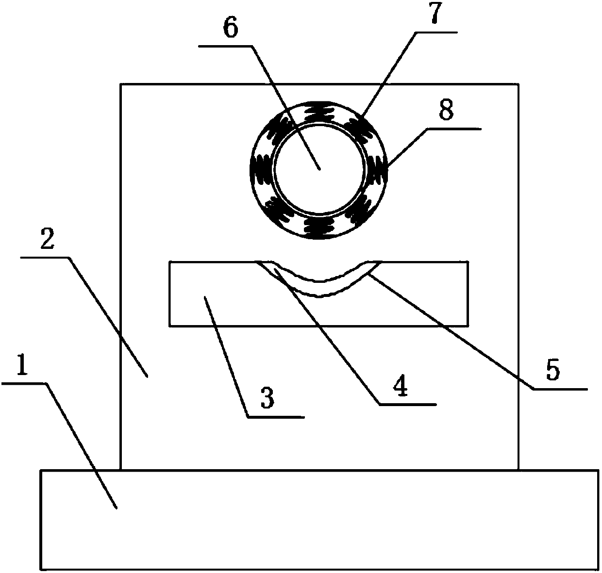
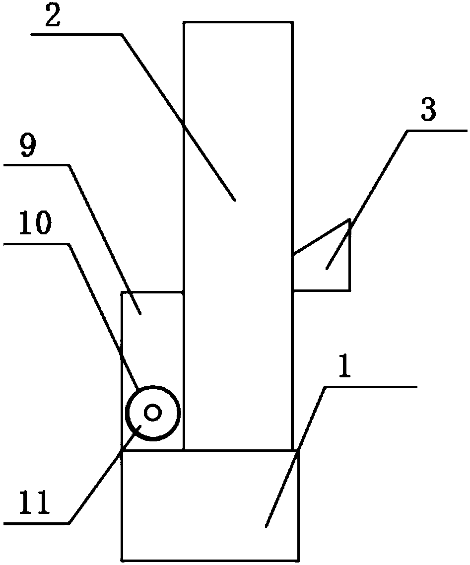
[0018] see Figure 1-3 , the present invention provides a technical solution: a suspension mechanism for placing a fuel oil gun, including a fixed base 1 and a device body 2, the upper surface of the fixed base 1 is welded with a device body 2, and the upper surface of the device body 2 is opened There is an insertion hole 6, a compression spring 7 is welded on the side wall of the insertion hole 6, and the other end of the compression spring 7 is fixedly bond...


PUM


Abstract

The invention discloses a suspending mechanism for an oil gun of a fueling machine, which comprises a fixed base and a device body. An insertion hole is opened above the front of the device body, and a compression spring is welded on the side wall of the insertion hole. The other end is fixedly bonded to the outer wall of the protective layer, the front of the device body is welded with a support horizontal block, the middle part of the support horizontal block is provided with an arc-shaped groove, and the inside of the device body is provided with a placement cavity. The lower surface inside the placement cavity is welded with a support plate, the upper surface of the support plate is provided with a scraper groove, the interior of the device body is installed with a connecting pipe, and the bottom of the opposite side of the device body is welded with an oil collection tank. The lower surface of the oil tank is welded and fixed to the upper surface of the fixed base. The side of the oil collection tank is provided with an oil discharge port. The bottom end of the storage chamber is connected with the connecting pipe. The use of gasoline avoids the waste of gasoline.

Description

technical field [0001] The invention relates to the technical field of refueling supporting equipment, in particular to a suspension mechanism for placing an oil gun of a refueling machine. Background technique [0002] With the continuous development of science and technology, cars have become an indispensable means of transportation for people's life and travel, and the demand for gasoline to provide fuel for cars has also increased, and gas stations have become more and more popular. The appearance of the oil gun solves the big problem in refueling, and it will not cause oil leakage. With the use of oil guns and changes in technology, oil gun racks have also changed, and oil gun racks with various functional styles have appeared. [0003] In the process of using the existing device, it is necessary to take off the oil gun many times every day, and the fixing between the oil gun and the placement frame causes certain wear and tear on the oil gun frame itself, and also has...

Claims


Application Information

Patent Timeline
IPC IPC(8): B67D7/54B67D7/42
CPCB67D7/54B67D7/42
Inventor 张金立
Owner 张金立
Learn More