
Method for carrying out connectivity detection crossing domains through LSP Ping/Traceroute

A connectivity detection and cross-domain technology, applied in the field of network communication, can solve the problem that LSPPing/Traceroute cannot be effectively applied, and achieve the effect of simple and reliable implementation.

Inactive Publication Date: 2018-04-13
FENGHUO COMM SCI & TECH CO LTD
View PDF4 Cites 1 Cited by
  • Summary
  • Abstract
  • Description
  • Claims
  • Application Information

AI Technical Summary

Problems solved by technology

[0021] The technical problem to be solved by the present invention is that the LSR in some Inter-AS and Inter-area deployment scenarios cannot rely on IP routing to forward, and sends the MPLS ECHO REPLY message message back to the source node LSR, which eventually leads to the failure of effective application of LSP Ping / Traceroute The problem

Method used

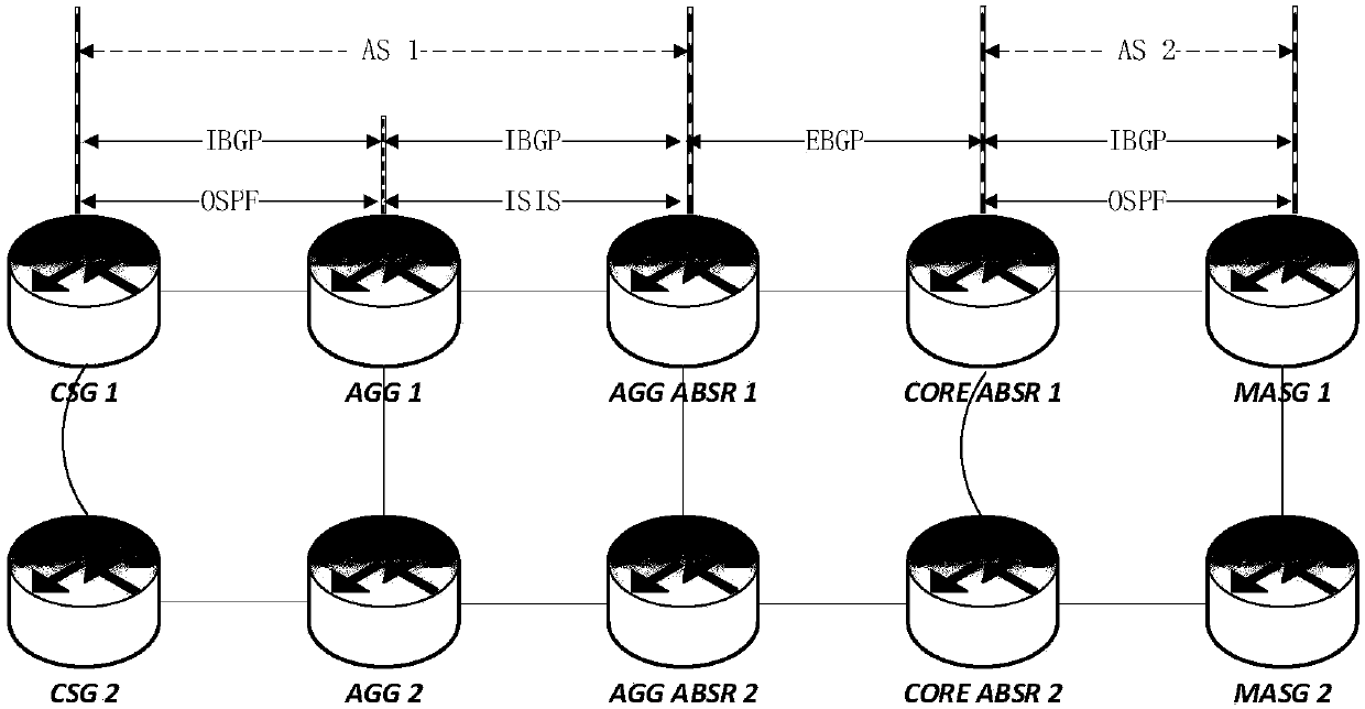

Image

  • Method for carrying out connectivity detection crossing domains through LSP Ping/Traceroute
  • Method for carrying out connectivity detection crossing domains through LSP Ping/Traceroute
  • Method for carrying out connectivity detection crossing domains through LSP Ping/Traceroute

Examples


Embodiment 1

[0056] This embodiment is an application using MPLS LSP Traceroute detection in an Inter-AS scenario.

[0057] Such as image 3 In the application scenario shown, the PE device PE1 at the origin site sends an MPLSECHO REQUEST detection message with a TTL value of 1, which is received by the P1 device after being transmitted on the LSP; because P1 is not an AS border, and the border flag is not set, it replies to the relay The node information is the next hop outbound interface IP: 10.23.0.2, K-bit is set to 0;

[0058] PE1 sends a detection message with a TTL value of 2, which is received by ASBR1 after being transmitted on the LSP; because ASBR1 is the boundary of AS1, and the boundary flag is set, the reply relay node information is the next hop outbound interface IP: 10.34.0.3, K-bit is set to 1;

[0059] PE1 sends a detection message with a TTL value of 3, which is received by ASBR2 after being transmitted on the LSP; because ASBR2 is the boundary of AS2, and the boundar...

Embodiment 2

[0065] This embodiment is an application of using MPLS LSP Ping detection in an Inter-AS scenario.

[0066] The relay node information viewed on the PE equipment PE1 at the starting site, it is assumed that the relay node information is saved and obtained by executing the LSP Traceroute operation in Embodiment 1;

[0067] PE1 sends an MPLS ECHO REQUEST detection message whose TTL value is greater than the LSP TTL, and after being transmitted on the LSP, it is received by LSPEgress station PE2. The MPLS ECHO REQUEST detection message carries the IP address of the relay node as the relay node information of the border node;

[0068] The PE device PE2 at the terminating site first sends the message to the nearest relay node ASBR2 according to the content of the relay node information, and sets the destination IP to 10.45.0.4;

[0069] After receiving the relay reply message, ASBR2 traverses the relay node information of the message, and then sends the message to the next relay no...


PUM


Abstract

The invention discloses a method for carrying out connectivity detection crossing domains through LSP Ping / Traceroute. The method comprises the steps that an end-to-end MPLS LSP is established betweentwo PE (Provider Edge) devices crossing the domains and an identifiers aer configured on boundary nodes of an AS or area as relay nodes; MPLS ECHO REQUEST detection requests sent by the PE device ata starting site of the LSP Ping / Traceroute carry IP addresses of the corresponding relay nodes as relay node information; and when the PE device at a termination site of the LSP Ping / Traceroute replyMPLS ECHO REPLY messages, the messages are replied according to the relay node information. According to the method, through relaying of the MPLS ECHO REPLY of the relay LSP Ping / Traceroute on the boundary nodes of the AS or area, the LSR (Label Switching Router) reply messages crossing the ASs or crossing the areas are reliably and stably forwarded back to the PE1 site through routes, and the LSPPing / Traceroute is guaranteed to be normal and effective in an Inter-AS and Inter-area scene.

Description

technical field [0001] The present invention relates to the technical field of network communication, in particular to a method for inter-domain connectivity detection using LSPPing / Traceroute, which is used for MPLS LSP deployed in Inter-AS or Inter-Area, using LSP Ping / Traceroute for connectivity detection. Background technique [0002] The main technical terms used in the present invention are explained as follows: [0003] PE equipment, Provider Edge, edge equipment on the network side; [0004] P equipment, Provider, core equipment; [0005] ASBR, Autonomous System Boundary Router, Autonomous System Boundary Router; [0006] CSG, Cell Site Gateway, base station gateway; [0007] ASG, Aggregate Service Gateway, convergent service gateway; [0008] MASG, Mobile Aggregate Service Gateway, Mobile Aggregate Service Gateway; [0009] LSR, Label Switching Router, Label Switching Router; [0010] Inter-AS, advanced inter-domain; [0011] Inter-area, between regions; [...

Claims


Application Information

Patent Timeline
IPC IPC(8): H04L12/26
Inventor 孟召辰
Owner FENGHUO COMM SCI & TECH CO LTD
Learn More