


Quick Research
Generate reliable direction feasibility study reports for your R&D in just a few steps.

Technical Q&A
Discover and master advanced knowledge NOW. Basics, ideas, possibilities, all at once.

Find Solutions
As an expert in R&D theories, this can generate solutions to your technical problems instantly.

Evaluate Feasibility
Analyze your overall solution with one click, know your potential R&D risks in advance.

Monitor Landscape
Get weekly tech updates, stay abreast of the latest tech innovations and key insights.
Dehumidification control method of rotary dehumidifier and rotary dehumidifier
A technology of a rotary dehumidifier and a control method, which is applied to the control input involving air characteristics, heating and ventilation control systems, space heating and ventilation control input, etc., can solve the problem that the rotary dehumidifier cannot automatically adjust the working state, etc. problem, to achieve the effect of improving the dehumidification effect is not obvious, good user experience, and the dehumidification speed is fast
- Summary
- Abstract
- Description
- Claims
- Application Information
AI Technical Summary
Problems solved by technology
Method used
Image

Examples
Embodiment 1
[0028]In this embodiment, in the setting step, R1 is the lower limit humidity threshold of the indoor air, T1 is the target temperature of the indoor air, R2 is the target humidity of the regeneration air outlet, T21 is the upper limit temperature threshold of the regeneration air outlet, and T2 is the lower limit temperature threshold of the regeneration air outlet, R3 is the predetermined humidity of the treatment air outlet, and T3 is the upper limit temperature threshold of the treatment air outlet. In the detection step, r1 is the real-time humidity of the indoor air, t1 is the real-time temperature of the indoor air, r2 is the real-time humidity of the regeneration air outlet, t2 is the real-time temperature of the regeneration air outlet, and r3 is the real-time humidity of the treatment air outlet , t3 is the real-time temperature of the process air outlet.
[0029] A dehumidification control method for a rotary dehumidifier in this embodiment includes the following st...
Embodiment 2
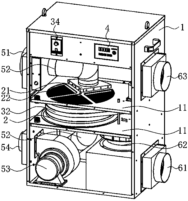
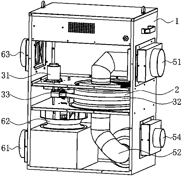
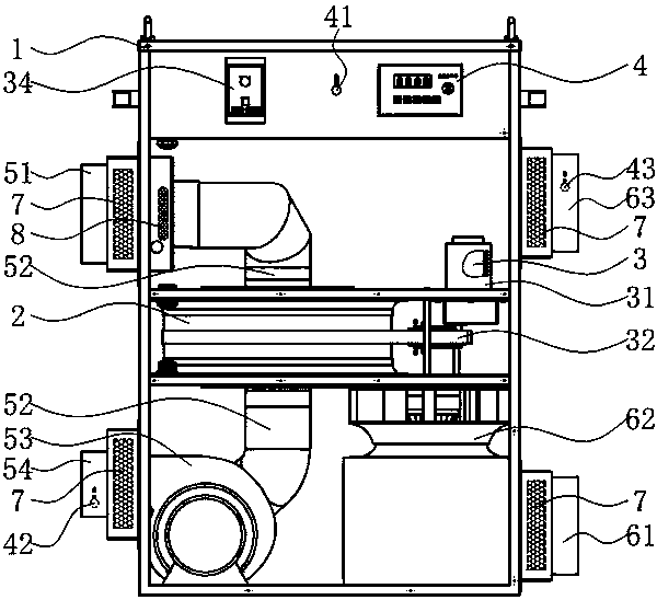
[0040] Such as Figure 1 to Figure 3As shown, a rotary dehumidifier in this embodiment includes a casing 1, a dehumidification wheel 2 assembled in the casing 1, a first sensor 41 for detecting the humidity and temperature of indoor air, and a dehumidification wheel 2 connected to a motor 3 for driving the rotation of the dehumidification wheel, and a controller 4 for controlling the working state of the wheel dehumidifier, the dehumidification wheel 2 includes a regeneration zone 21 and a moisture absorption zone 22; the two ends of the regeneration zone 21 A regenerated air inlet channel and a regenerated air outflow channel are provided, a heater 8 is arranged in the regenerated air inlet channel, a second sensor 42 for detecting the humidity and temperature of the regenerated air outlet is arranged in the regenerated air outflow channel, and it also includes A regenerative wind blower 53 for driving the regenerative wind flow; the two ends of the moisture absorption zone 2...
PUM
 Abstract
Description
Claims
Application Information
 - R&D Engineer
- R&D Manager
- IP Professional
- Industry Leading Data Capabilities
- Powerful AI technology
- Patent DNA Extraction
Browse by: Latest US Patents, China's latest patents, Technical Efficacy Thesaurus, Application Domain, Technology Topic, Popular Technical Reports.
© 2024 PatSnap. All rights reserved.Legal|Privacy policy|Modern Slavery Act Transparency Statement|Sitemap|About US| Contact US: help@patsnap.com