
Automobile damping and energy storage mechanism adapted for big impact force

A technology of automobile shock absorption and energy storage mechanism, applied in shock absorbers, springs/shock absorbers, shock absorbers, etc., can solve the problems of ineffective identification, single function, and shortening the service life of shock absorbers.

Inactive Publication Date: 2018-04-13
DONGGUAN SONGYAN ZHIDA IND DESIGN CO LTD
View PDF5 Cites 1 Cited by
  • Summary
  • Abstract
  • Description
  • Claims
  • Application Information

AI Technical Summary

Problems solved by technology

[0002] At present, the existing shock absorption technology uses the shock absorber to complete the absorption and shock absorption of the impact force, and uses the damper to accelerate the attenuation of the vibration energy. The different impact forces generated under different working conditions are only reduced by a single shock absorption method. Absorbing the energy of impact has a single function and cannot effectively convert and utilize the energy of impact; in addition, the existing shock absorption technology cannot store the energy of vibration, resulting in a waste of energy. Under extreme working conditions, the traditional shock absorption technology cannot effectively identify extreme working conditions, and then it is easy to cause certain mechanical damage to the structure inside the shock absorber under the instantaneous large impact force, reducing the shock absorber service life

Method used


Image

  • Automobile damping and energy storage mechanism adapted for big impact force
  • Automobile damping and energy storage mechanism adapted for big impact force
  • Automobile damping and energy storage mechanism adapted for big impact force

Examples


Embodiment Construction

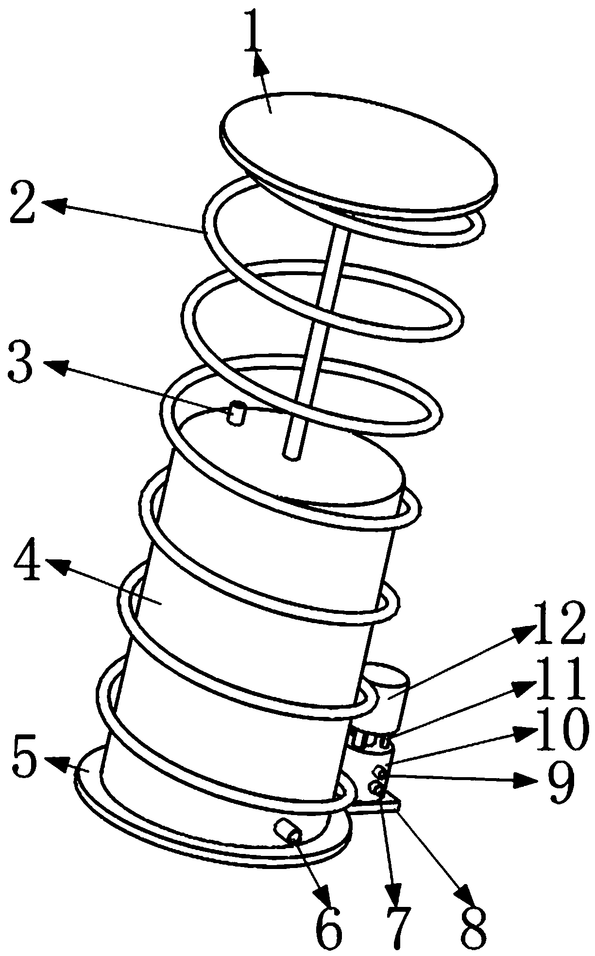
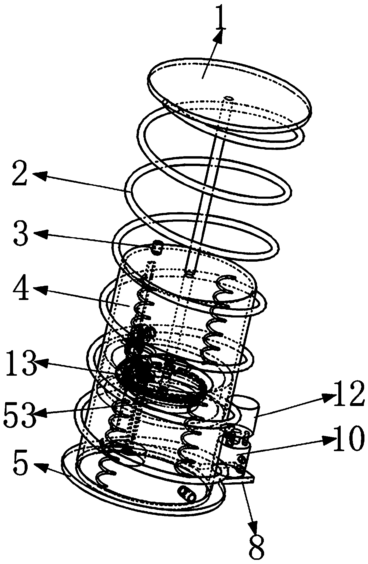
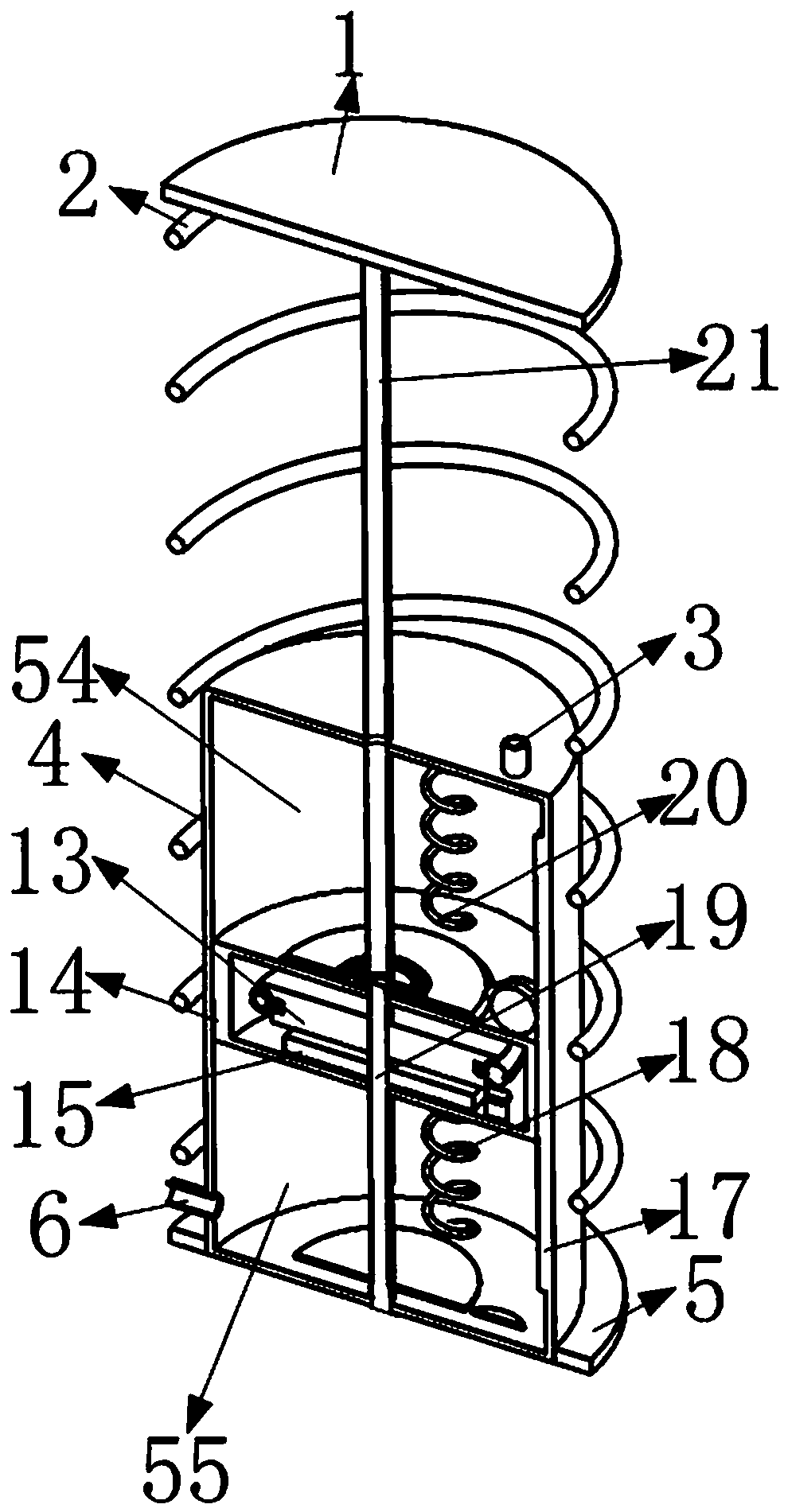
[0012] Such as figure 1 , 2 , 3, it includes a first baffle 1, a damping spring 2, a first nozzle 3, a damping shell 4, a second baffle 5, a second nozzle 6, a third nozzle 7, a fixed plate 8, First cavity 54, second cavity 55, fourth nozzle 9, air motor 10, support bar 11, generator 12, piston mechanism 53, first fixed block 16, rack 17, first spring 18, the first Two springs 20, push sleeve 21, first T-shaped ring groove 22, such as figure 1 As shown, wherein the second baffle plate 5 is installed on the outer circular surface of one end of the damping shell 4; one end of the fixed plate 8 is installed on the outer circular surface of the second baffle plate 5; as figure 1 As shown, one end of the air motor 10 is installed on the end face of the fixed plate 8; figure 1 As shown, the third nozzle 7 and the fourth nozzle 9 are installed on the air motor 10; as figure 1 As shown, the generator 12 is installed on the air motor 10 through three support bars 11 evenly distribu...


PUM


Abstract

The invention belongs to the technical field of automobile damping and energy storage, and particularly relates to an automobile damping and energy storage mechanism adapted for big impact force. Theautomobile damping and energy storage mechanism adapted for the big impact force includes a first baffle, a damping spring, a first nozzle, a damping shell, a second baffle, a second nozzle, a third nozzle, a fixing plate and so on; and a piston mechanism can move up and down in the damping shell when subjected to impact force, high-pressure inert gas in the damping shell enters an air motor to have a role through compressing of the piston mechanism, and the air motor drives an electric generator to generate electricity. Impactive energy is stored by the air motor and the electric generator when the automobile damping and energy storage mechanism adapted for the big impact force is under a normal running condition, and the purpose of rapidly absorbing impact force and rapidly declining damping can be realized; the structure is simple and compact, energy conservation is high, and the automobile damping and energy storage mechanism adapted for the big impact force has a better actual useeffect; and the problem that the inner structure of a damper is subjected to mechanical damage when the damper is subjected to momentary surging impact force is solved, the effect to protect the damper in an emergency can be performed, and the service life of the damper is prolonged.

Description

Technical field [0001] The invention relates to an automobile shock-absorbing energy-storage mechanism adaptable to large impact force. Background technique [0002] At present, the existing shock absorption technology uses the shock absorber to complete the absorption and shock absorption of the impact force, and uses the damper to accelerate the attenuation of the vibration energy. The different impact forces generated under different working conditions are only reduced by a single shock absorption method. Absorbing the energy of impact has a single function and cannot effectively convert and utilize the energy of impact; in addition, the existing shock absorption technology cannot store the energy of vibration, resulting in a waste of energy. Under extreme working conditions, the traditional shock absorption technology cannot effectively identify extreme working conditions, and then it is easy to cause certain mechanical damage to the structure inside the shock absorber u...

Claims


Application Information

Patent Timeline
IPC IPC(8): F16F13/00
CPCF16F13/007F16F2230/0023F16F2232/08F16F2238/026
Inventor 王杰
Owner DONGGUAN SONGYAN ZHIDA IND DESIGN CO LTD
Learn More