A kind of in-situ cast-in-place construction method for bridges

A construction method and in-situ technology, applied in the direction of bridges, bridge construction, bridge materials, etc., can solve the problems of high difficulty, difficult quality control, long waiting time, etc., so as to reduce the project cost, shorten the construction period, and ensure the quality of binding Effect

Active Publication Date: 2019-03-15
ZHENGZHOU NEW DAFANG HEAVY IND & TECH
View PDF10 Cites 0 Cited by
  • Summary
  • Abstract
  • Description
  • Claims
  • Application Information

AI Technical Summary

Problems solved by technology

[0004] The above seven processes must be carried out in sequence, which leads to low work efficiency and high construction costs; and the steel bars are bound on site in the formwork cavity of the formwork, so quality control is difficult; the inner formwork needs to wait until the end and the web steel bars are formed manually, which is difficult and fast Slow, long waiting time for different types of work, insufficient utilization of labor force, long construction period, high construction cost, and poor economy
For example, the previous invention patent ZL200810147793.4 discloses a casting-in-place construction method for bridge shutters, which mainly includes: a. steel bar construction, b. shutter cast-in-place mobile formwork installation, c. concrete pouring, d. demolition Formwork, e. There are five steps to move the formwork, and each process cannot be carried out at the same time. The construction efficiency is low and the cycle is long. Therefore, an in-situ cast-in-place construction method that can better improve construction efficiency is needed

Method used


Image

  • A kind of in-situ cast-in-place construction method for bridges
  • A kind of in-situ cast-in-place construction method for bridges
  • A kind of in-situ cast-in-place construction method for bridges

Examples


Embodiment Construction

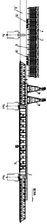
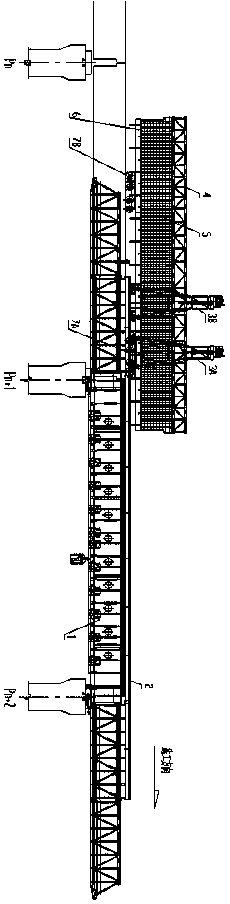
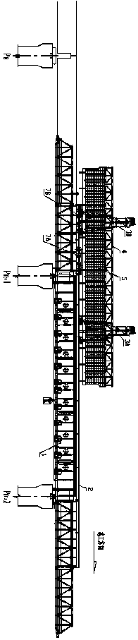
[0052] The present invention will be further described below in conjunction with accompanying drawing of the present invention:

[0053] Such as Figure 1 to Figure 14As shown, the present invention is based on the down-supporting mobile formwork. The down-supporting mobile formwork is a mobile formwork whose main structure is supported below the concrete bridge. The supporting type mobile formwork is an embodiment to describe the present invention, and "Pn" "Pn+1" "Pn+2" in the illustration represents the pier number, indicating the formwork construction pier span. The term "front" used among the present invention refers to the same direction as the construction direction, and the term "back" refers to the direction opposite to the construction direction; the term "longitudinal bridge direction" refers to the length direction of the bridge, and the term "horizontal bridge" "To" refers to the width direction of the bridge.

[0054] Such as Figure 1 to Figure 14 As shown, i...


PUM


Abstract

The invention relates to a bridge in-situ cast-in-situ construction method. The bridge in-situ cast-in-situ construction method is implemented based on a bottom bearing type movable mold frame, and the work procedure of steel bar binding and the work procedures of bridge pouring, curing and tensioning are implemented simultaneously. According to the bridge in-situ cast-in-situ construction method,in cast-in-situ construction of the movable formwork, the modes that reinforcement cage binding and inner mold splicing are conducted on the bridge face, and a reinforcement cage is dragged and hoisted to the position above a mold bed to fall for mounting are adopted, sequential construction in an original construction method is changed into parallel construction, the beam manufacturing work efficiency of the movable mold frame can be effectively improved, and the bridge in-situ cast-in-situ construction period is greatly shortened; and the whole reinforcement cage is prefabricated in a semi-industrialization mode, the binding quality and efficiency are effectively ensured, and bridge in-situ cast-in-situ construction can be well matched.

Description

technical field [0001] The invention relates to a bridge construction method, in particular to a bridge in-situ cast-in-place construction method. Background technique [0002] In bridge construction, bridge cast-in-place construction is widely used. It has the advantages of relatively large single pouring volume, less disassembly and assembly of equipment, simple and convenient forward operation of equipment, and less shifting times. It can be effectively Complete a series of construction procedures such as the adjustment of formwork, the installation and binding of steel bars, the pouring of concrete, and the prestressed tension. However, according to the traditional construction method commonly used at present, the construction period of the mobile formwork cast-in-situ construction of a one-hole bridge is relatively long, about 16 days per hole, and the basic process is as follows: [0003] [0004] The above seven processes must be carried out in sequence, which lea...

Claims


Application Information

Patent Timeline
Patent Type & Authority Patents(China)
IPC IPC(8): E01D21/00E01D21/06E01D101/20
CPCE01D21/00E01D21/06E01D2101/20
Inventor 张志华曹长兴陈德利马涛代宇周治国吴国梅田凤学张艳丽刘舒馨卫森祁磊张永力付晓帆曲长立
Owner ZHENGZHOU NEW DAFANG HEAVY IND & TECH
Why Eureka
Try Eureka