High-voltage wiring box convenient to assemble and disassemble and assembling and disassembling method of high-voltage wiring box

A high-voltage wiring and easy-to-install technology, which is applied to electrical devices, transportation and packaging, electric vehicles, etc., can solve problems such as electric shock, equipment damage, and inconvenient operation

Pending Publication Date: 2018-04-13
SHENZHEN CHOGORI TECH CO LTD
View PDF0 Cites 0 Cited by
  • Summary
  • Abstract
  • Description
  • Claims
  • Application Information

AI Technical Summary

Problems solved by technology

Its disadvantages are: several screws are screwed in, there is no stop structure, the degree of tightness of each screw is different, resulting in poor overall sealing, water and dust in the external environment are easy to enter the interior, and the long-term waterproof performance cannot be achieved; screwing in at the same time The installation method of inserting several screws, the operation process of installation and disassembly requires a large space, and the operation is inconvenient; the shielding connection has no switch function, and when live operation occurs, electric shock may occur, causing equipment damage or even personal injury

Method used


Image

  • High-voltage wiring box convenient to assemble and disassemble and assembling and disassembling method of high-voltage wiring box
  • High-voltage wiring box convenient to assemble and disassemble and assembling and disassembling method of high-voltage wiring box
  • High-voltage wiring box convenient to assemble and disassemble and assembling and disassembling method of high-voltage wiring box

Examples


Embodiment Construction

[0027] The present invention will be described in further detail below in conjunction with accompanying drawing:

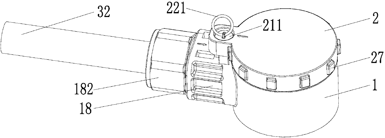
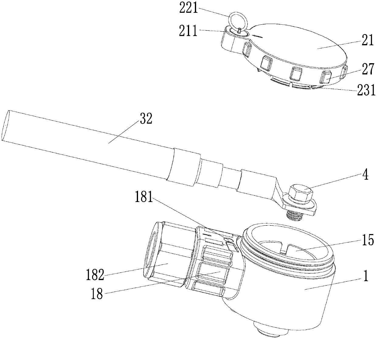
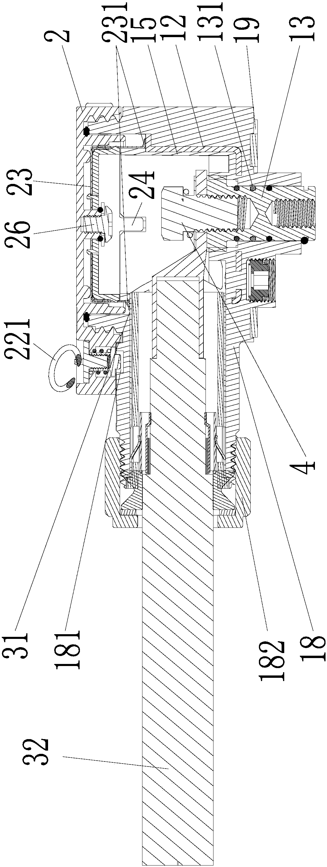
[0028] see Figure 1 to Figure 3 As shown, the high-voltage junction box that is convenient to install and disassemble includes a base 1, an upper cover 2 connected to the base 1, the base 1 is installed on the panel of the equipment, and the wire harness 32 enters the inner cavity of the base 1 after passing through the gland 18 , and connected to the terminal post 13 located in the inner cavity of the base 1 through the connecting screw 4, the upper cover 2 is detachably connected to the base 1, the radial protrusion of the upper cover 2 is provided with a stop lock 22, and the base 1 The corresponding recess is provided with a stop groove 181. When the upper cover 2 is screwed to the set position, the stop lock 22 of the upper cover 2 slides into the stop groove 181 of the base to lock, and the upper cover 2 cannot be twisted any more. When it needs to be disa...


PUM


Abstract

The invention relates to a high-voltage wiring box convenient to assemble and disassemble and an assembling and disassembling method of the high-voltage wiring box. The high-voltage wiring box convenient to assemble and disassemble comprises a base and an upper cover connected with the base, wherein the base is mounted on a panel of equipment; a wiring harness penetrates through a cable gland to enter an inner cavity of the base, and is connected to a wiring terminal located in the inner cavity of the base through a connecting screw rod; the upper cover is detachably connected with the base; astop lock is arranged at a radial protruding position of the upper cover; a stop groove is formed in a corresponding concave part of the base; when the upper cover is screwed to a set position, the stop lock of the upper cover slides into the stop groove in the base to be locked, and the upper cover cannot be screwed; and when disassembling is required, a pull ring of the stop lock is pulled up upwards by hands, so that unlocking can be performed, and the upper cover can be unscrewed. The assembling and disassembling method comprises the following steps of (1) during assembling, rotatably combining the upper cover with the base, and enabling a pin nail of the stop lock to slide in the stop groove in the base, so as to perform automatic stopping and locking; and (2) during disassembling, pulling up the pull ring of the stop lock, and enabling the pin nail of the stop lock to leave the stop groove, so as to perform automatic unlocking and unscrew the upper cover.

Description

technical field [0001] The invention relates to a high-voltage power supply connection device for a power battery of a new energy vehicle, in particular to a high-voltage junction box which is easy to install and disassemble and a disassembly method thereof. Background technique [0002] At present, new energy vehicles have become an inevitable trend in the development of the automotive industry, and the application of charging equipment on electric vehicles has become more and more important to people. High-energy power batteries installed on electric vehicles require connectors that can be connected and shielded with high-voltage power supplies, and the connectors are used in vibration and exposed environments for a long time, and the waterproof and dustproof effects are poor, and they are prone to electromagnetic interference. The normal operation of the components poses a safety hazard. The structure of the high-voltage junction box disclosed in the prior art is as foll...

Claims


Application Information

Patent Timeline
IPC IPC(8): B60L3/00B60R16/02
CPCB60L3/00B60R16/0215
Inventor 唐努利张平红
Owner SHENZHEN CHOGORI TECH CO LTD
Why Eureka
Try Eureka