
Automatic troweling machine

A plastering machine and automatic technology, which is applied to mixers, mixer accessories, mixers with rotary stirring devices, etc., can solve the problems of unreasonable structural design, high labor intensity and low work efficiency of plastering machines.

Pending Publication Date: 2018-04-10
深圳市森博机器人有限公司
View PDF0 Cites 5 Cited by
  • Summary
  • Abstract
  • Description
  • Claims
  • Application Information

AI Technical Summary

Problems solved by technology

The traditional slurry smearing and covering process is mainly to smear the slurry on the surface of the blank wall by manually holding a special tool. The workload is large, the work efficiency is low, the labor intensity is high, and the construction quality is difficult to guarantee.
[0003] With the increasing degree of mechanization in the construction field, some fully automatic mechanical plastering machines have appeared. Although the mechanized operation can greatly reduce the labor intensity of construction workers and provide a guarantee for the consistency and standardization of construction quality, However, due to the unreasonable design of the structural structure of this type of plastering machine, the quality of its plastering work cannot be guaranteed, and the practical performance of the plastering machine is also seriously reduced.

Method used

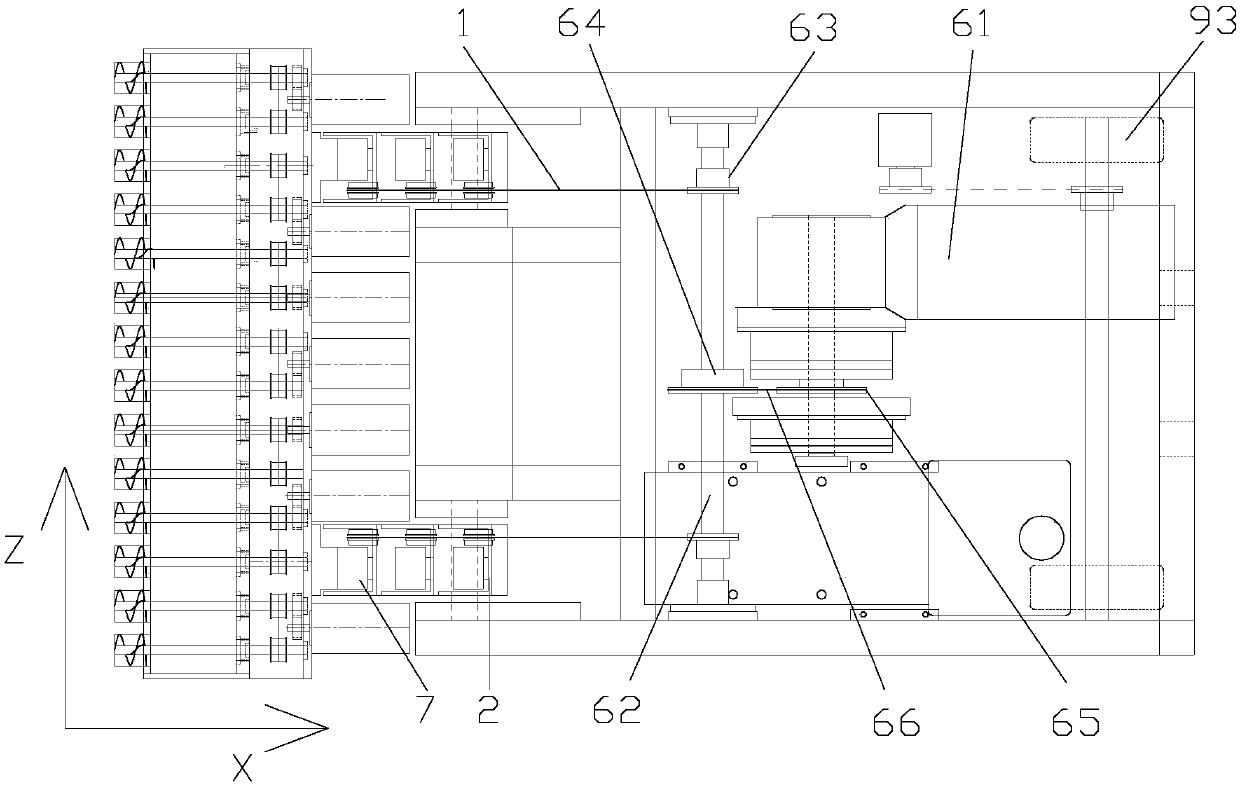
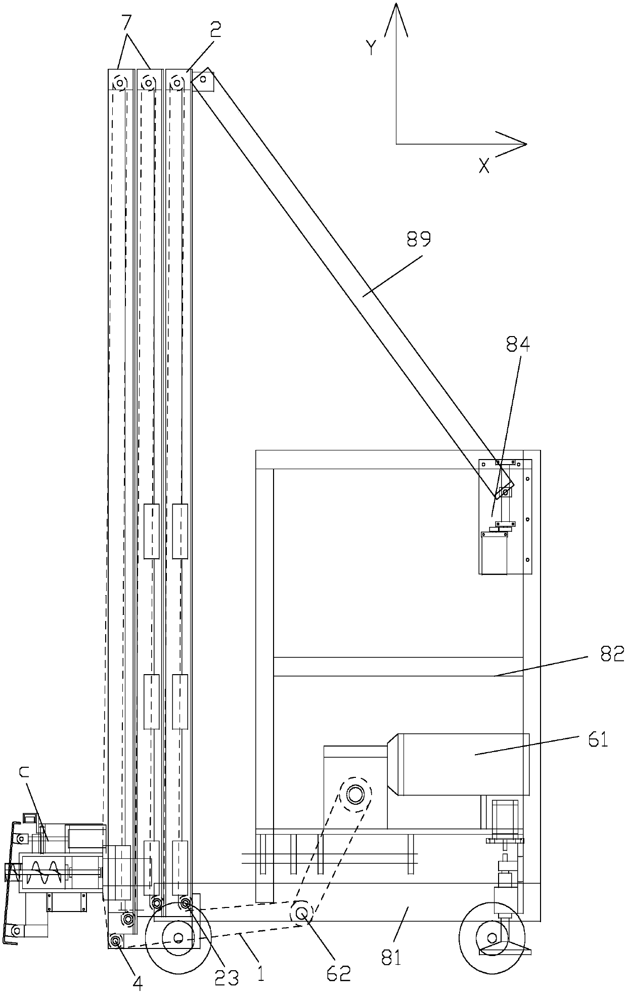

Image

  • Automatic troweling machine
  • Automatic troweling machine
  • Automatic troweling machine

Examples


Embodiment Construction

[0033] The embodiments of the present invention will be described in detail below with reference to the accompanying drawings, but the present invention can be implemented in many different ways defined and covered by the claims.

[0034] like Figure 1 to Figure 10 Shown, a kind of automatic plastering machine provided by the present embodiment, it comprises:

[0035] A traveling frame assembly a that is used as the body of the entire machine and can drive the entire machine to move (especially on a level ground);

[0036] A traction lifting assembly b, which includes at least one lifting column device installed on the front end of the traveling frame assembly a along the Y-axis direction and a traction column device installed on the rear end of the traveling frame assembly a Drive device; wherein, the lifting column device includes a traction transmission belt 1, a supporting column 2 installed on the front end of the traveling machine base assembly a, and a lifting column ...


PUM


Abstract

The invention relates to the technical field of constructional engineering machinery, in particular to an automatic troweling machine. The automatic troweling machine comprises a walking machine seatassembly, a traction lifting assembly and a discharging machine head assembly. The traction lifting assembly comprises a lifting stand column device and a traction driving device, and the lifting stand column device comprises a traction driving belt, a supporting stand column and a lifting stand column set; and the discharging machine head assembly comprises a slurry stock bin with the front surface being provided with a discharging pipe, a spiral material conveying device installed in the slurry stock bin and a troweling plate installed on the front surface side of the slurry stock bin, a discharging port is formed in the troweling plate, a pressure sensor used for conducting pressure detection is further installed at the position, corresponding to the discharging port, of the troweling plate, and a slurry conveying hose is further installed on the slurry stock bin. According to the automatic troweling machine, the structure is simple, moving is flexible, material supplying is precise, adjustability is high, the operating efficiency is high, the operating range is wide, the flatness of wall surface troweling is high, and the automatic troweling machine has high practical value andmarket promotion value.

Description

technical field [0001] The invention relates to the technical field of construction machinery, in particular to an automatic plastering machine. Background technique [0002] The slurry (such as mortar or mortar, etc.) smearing and covering process on the surface of the building is an important construction project in the construction field. The slurry is applied on the surface to achieve the purpose of improving the indoor environment of the building or improving the architectural performance of the building such as heat insulation, moisture resistance and weather resistance. The traditional slurry smearing and covering process is mainly to smear the slurry on the surface of the blank wall by manually holding a special tool. The workload is large, the work efficiency is low, the labor intensity is high, and the construction quality is difficult to guarantee. [0003] With the increasing degree of mechanization in the construction field, some fully automatic mechanical plas...

Claims


Application Information

Patent Timeline
IPC IPC(8): E04F21/08B01F7/08B01F15/02B01F15/00
CPCB01F27/2322B01F27/721B01F35/43B01F35/754551B01F2101/28Y02P70/10
Inventor 孙镇何昌秋杜加才
Owner 深圳市森博机器人有限公司
Learn More