A supercritical reaction device
A supercritical and reactor technology, applied in the control of water treatment parameters, chemical instruments and methods, water/sludge/sewage treatment, etc., can solve the problems of long processing time and high cost, and achieve the problem of avoiding bursting and low cost , to achieve the effect of efficient utilization
- Summary
- Abstract
- Description
- Claims
- Application Information
AI Technical Summary
Problems solved by technology
Method used
Image
Examples
Embodiment 1
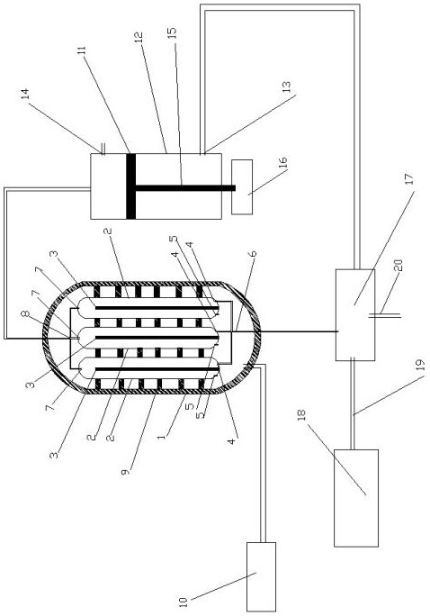
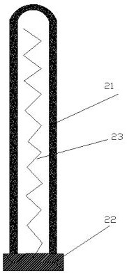
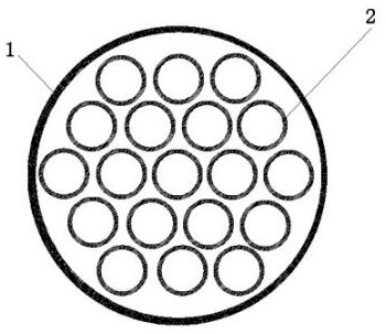
[0025] Such as figure 1 The shown device comprises a pressure vessel 1, at least one reactor 2 arranged in the pressure vessel, a pressure temperature sensor and a pressure control system; the reactor 2 is provided with a water inlet and a water outlet controlled by a water inlet electromagnetic control valve 4 The water outlet / air port controlled by the electromagnetic control valve 7, the reactor 2 is provided with a heater 3;
[0026] The pressure and temperature sensors include a first pressure and temperature sensor (not shown in the figure) arranged in the pressure vessel and a second pressure and temperature sensor 5 arranged in the reactor;
[0027] The first pressure temperature sensor and the second pressure temperature sensor 5 are connected to the pressure control system 10; the pressure control system 10 controls the pressure in the pressure vessel 1 and the reactor 2 to be consistent according to the pressure signal data collected by the pressure temperature sens...
Embodiment 2
[0031] Such as figure 1As shown, the difference between this embodiment and Embodiment 1 is that it also includes a decompression buffer device, and the decompression buffer device is composed of a piston 11, a cylinder 12, a piston push rod 15 and a piston control motor 16, and the cylinder 12 There is a water inlet of the decompression buffer device, a water outlet 13 of the decompression buffer device and a control valve 14, the water inlet of the decompression buffer device is connected to the water outlet / gas port of the reactor, and the water outlet 13 of the decompression buffer device is connected to a conventional condensing device The piston control motor 16 controls the piston push rod 15 to push the piston 11 to move, controls the pressure in the cylinder 12, and controls the valve 14 to carry out negative pressure feeding and decompression discharging.
Embodiment 3
[0033] Such as figure 1 As shown, the only difference between this embodiment and Embodiment 2 is that it also includes a condensation and heat recovery device and a preheating device. In this embodiment, the condensation and heat recovery device and the preheating device adopt an integrated device 17; the integrated structure is more It is beneficial to the heat exchange between the condensation and the heat recovery device part and the preheating device part, and reduces heat loss. The condensation and heat recovery device is partly connected to the water outlet of the decompression buffer device, and the preheating device is partly connected to the waste liquid pool 18 to be treated and the water inlet of the reactor 2 .
[0034] The specific use process and working principle of the device of this embodiment are as follows:
[0035] Step 1. Close the control valve 14 of the decompression buffer device, and drive the piston push rod 15 of the decompression buffer device thr...
PUM
 Abstract
Description
Claims
Application Information
 - R&D
- Intellectual Property
- Life Sciences
- Materials
- Tech Scout
- Unparalleled Data Quality
- Higher Quality Content
- 60% Fewer Hallucinations
Browse by: Latest US Patents, China's latest patents, Technical Efficacy Thesaurus, Application Domain, Technology Topic, Popular Technical Reports.
© 2025 PatSnap. All rights reserved.Legal|Privacy policy|Modern Slavery Act Transparency Statement|Sitemap|About US| Contact US: help@patsnap.com


