Magnetic attraction locating automobile internal star wheel center hole polishing device

A technology of inner star wheel and center hole, which is applied in the direction of grinding drive device, grinding/polishing safety device, grinding machine, etc. It can solve the problems of laborious and laborious, reduced grinding efficiency, and difficult fixing of fixtures, etc., and achieves convenient, fast and stable operation good sex effect

Active Publication Date: 2018-04-10
安徽赢廷智能装备有限公司
View PDF10 Cites 4 Cited by
  • Summary
  • Abstract
  • Description
  • Claims
  • Application Information

AI Technical Summary

Problems solved by technology

[0003] At present, for the processing of the smoothness of the center hole of the inner star wheel of the universal joint, a grinding disc is usually used for polishing. However, due to the complex structure of the inner star wheel, it is difficult to fix it with conventional fixtures, resulting in shaking during the grinding process. As a result, the quality of its grinding is affected, resulting in a low finish in the center hole of the inner star wheel, which cannot meet the needs of installation, and the existing fixtures are usually manually operated, and the clamping and removal operations of the inner star wheel are complicated, resulting in its grinding efficiency. Reduced, laborious and laborious, not conducive to the convenient operation of grinding the center hole of the inner star wheel of the car

Method used


Image

  • Magnetic attraction locating automobile internal star wheel center hole polishing device
  • Magnetic attraction locating automobile internal star wheel center hole polishing device
  • Magnetic attraction locating automobile internal star wheel center hole polishing device

Examples


Embodiment Construction

[0021] The following will clearly and completely describe the technical solutions in the embodiments of the present invention with reference to the accompanying drawings in the embodiments of the present invention. Obviously, the described embodiments are only some, not all, embodiments of the present invention. Based on the embodiments of the present invention, all other embodiments obtained by persons of ordinary skill in the art without making creative efforts belong to the protection scope of the present invention.

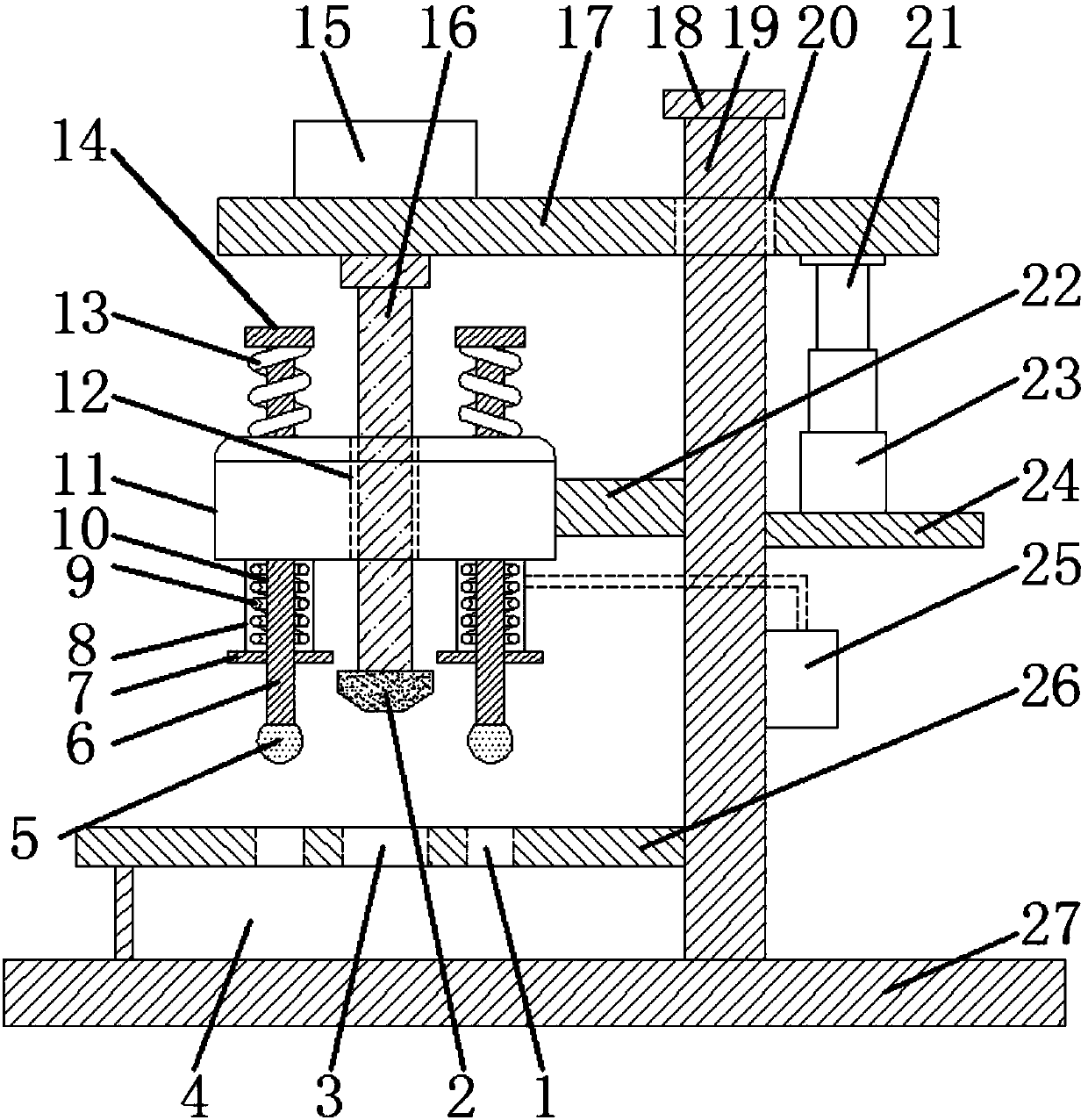
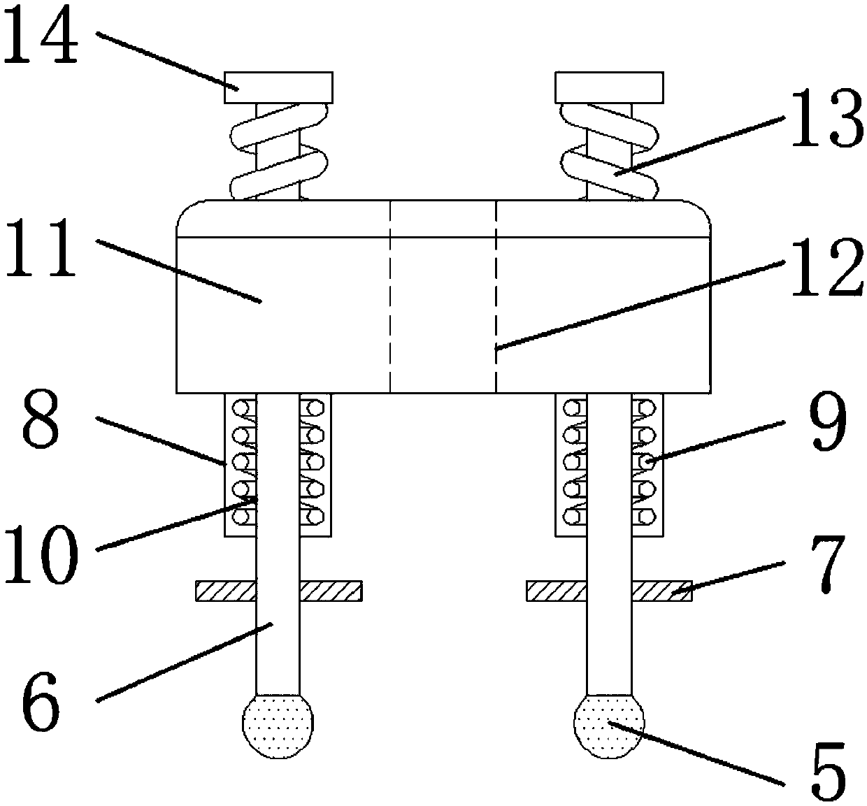
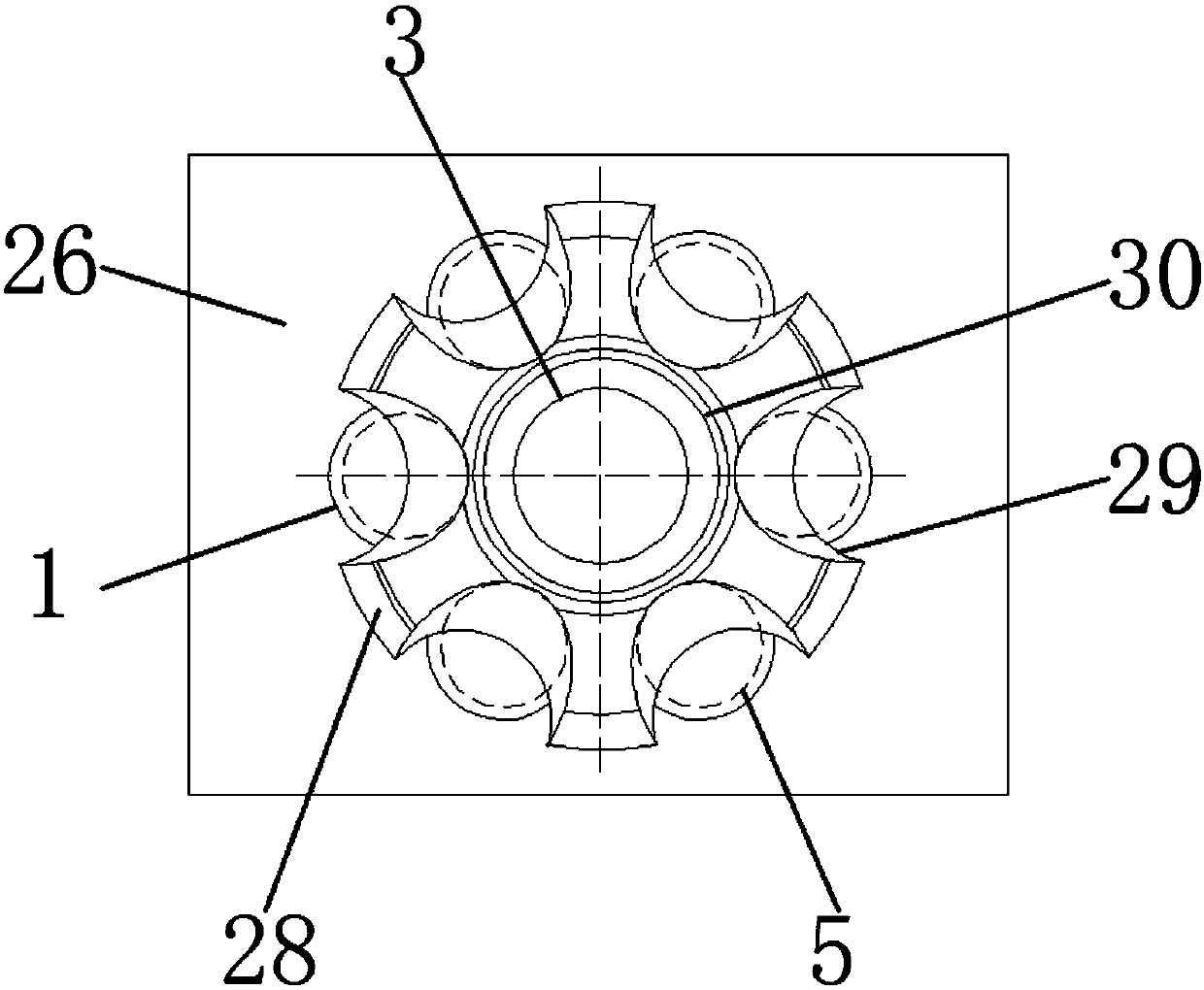
[0022] see Figure 1~3 , in the embodiment of the present invention, a kind of center hole grinding device of the inner star wheel of a car with magnetic suction positioning, the stopper 7, the electromagnetic guide block 11, the rotating shaft 16, the telescopic rod 21, the base 27 and the inner star wheel 28, the base The 27 upper ends are fixedly connected to the column 19, and the top of the column 19 is fixedly connected to the limit block 18. The column ...


PUM


Abstract

The invention discloses a magnetic attraction locating automobile internal star wheel center hole polishing device which comprises stop blocks, an electromagnetic guide block, a rotating shaft, a telescopic rod, a base and an internal star wheel; the upper end of the base is fixedly connected with an upright column; the top end of the upright column is fixedly connected with a limiting stopper; the part, below the limiting stopper, of the upright column is sleeved with an upper beam plate; a motor is arranged at the part, on one side of the upright column, of the top end of the upper beam plate; the bottom end of the motor is connected with the rotating shaft; a grinding sheet is arranged at the bottom end of the rotating shaft; the middle part of the upright column is connected with a fixing bracket; the electromagnetic guide block is arranged on the fixing bracket; electromagnet sleeves are arranged at the bottom of the electromagnetic guide block; inner guide cylinders are arrangedin the electromagnet sleeves; a coil is wound between each inner guide cylinder and the corresponding electromagnet sleeve; and iron-core rods penetrate through the inner guide cylinders. Height adjustment is realized when the grinding sheet carries outer rotating polishing; ball way limiting balls at the bottom ends of the iron-core rods are clamped into ball ways of the internal star wheel, so that clamping and limiting on the internal star wheel are realized, and the stability is good; and operation is convenient and quick, and no manual clamping or fixing is required.

Description

technical field [0001] The invention relates to the technical field of auto parts processing, in particular to a center hole grinding device for an inner star wheel of an automobile positioned by magnetic suction. Background technique [0002] The ball cage and the inner star wheel are the key parts of the universal joint, and the universal joint is an important part in the transmission system of a car. On a front-wheel drive car, the front axle is equipped with a constant velocity universal The function of the joint is to transmit the power of the engine from the transmission to the driving wheel of the car, meet the requirements of the outer end corner of the drive shaft of the car, transmit the power of the engine to the wheels stably and reliably, compensate the beating of the suspension at the inner end of the car, and meet the requirements of the drive shaft. High-speed driving requirements for cars. According to the different section types, it can be divided into RE,...

Claims


Application Information

Patent Timeline
Patent Type & Authority Applications(China)
IPC IPC(8): B24B5/48B24B41/06B24B41/02B24B27/00B24B55/06B24B41/00B24B47/06
CPCB24B5/48B24B27/0015B24B41/005B24B41/02B24B41/06B24B47/06B24B55/06
Inventor 赵春城吴敏芳周朱晨刘金杰翟明明
Owner 安徽赢廷智能装备有限公司
Why Eureka
Try Eureka