
Two-side flow variable sewage source heat pump unit and operation method thereof

A sewage source heat pump and flow technology, which is used in heat pumps, fluid heaters, refrigerators, etc., can solve the problems of high requirements for intermediate heat exchangers, low efficiency, and high requirements for sewage treatment, so as to increase the temperature difference between incoming and outgoing water, work Clear principle and novel structure

Active Publication Date: 2018-04-06
YANGZHOU UNIV
View PDF4 Cites 3 Cited by
  • Summary
  • Abstract
  • Description
  • Claims
  • Application Information

AI Technical Summary

Problems solved by technology

The former performs multiple filtrations on the sewage, and after degreasing, it directly enters the sewage source heat pump. The operating efficiency of the system is high, but the requirements for sewage treatment are high; The refrigerant enters the water source heat pump unit again, but the requirements for the intermediate heat exchanger are high, the system is reliable in operation, and the efficiency is slightly low

Method used


Image

  • Two-side flow variable sewage source heat pump unit and operation method thereof
  • Two-side flow variable sewage source heat pump unit and operation method thereof
  • Two-side flow variable sewage source heat pump unit and operation method thereof

Examples


Embodiment Construction

[0023] The present invention will be further described below in conjunction with accompanying drawing:

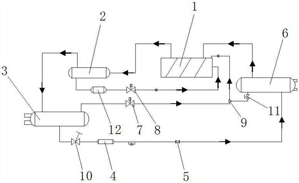
[0024] Such as figure 1 As shown, a double-sided variable flow sewage source heat pump unit includes connecting pipelines; the sewage source heat pump unit consists of a screw heat pump compressor 1, an oil separator 2, a variable flow condenser 3, a dry filter 4, and an electronic Expansion valve 5, variable flow flooded evaporator 6, evaporator oil return solenoid valve 7, oil separation oil return solenoid valve 8, ejector pump 9, liquid circuit stop valve 10, evaporator oil return stop valve 11 and oil filtration The devices 12 are connected to each other by connecting pipelines;

[0025] Such as figure 1 As shown, a double-sided variable flow sewage source heat pump unit, screw heat pump compressor 1, oil separator 2, variable flow condenser 3, electronic expansion valve 5 and variable flow flooded evaporator 6 are connected in series connection; between the screw h...


PUM


Abstract

The invention discloses a two-side flow variable sewage source heat pump unit and an operation method thereof, and belongs to the technical field of energy conservation and emission reduction. The two-side flow variable sewage source heat pump unit is formed through connecting a variable-flow flooded evaporator, a screw type heat pump compressor, an oil separator, a variable-flow condenser, a dryfilter, an electronic expansion valve, and the like. According to the two-side flow variable sewage source heat pump unit, the structure is novel, the working principle is clear, and compared with theprior art, the two-side flow variable sewage source heat pump unit has the advantages that the heat exchange process of hot water of the condenser can be automatically changed according to the quantity and temperature condition of sewage and the temperature condition of hot water, and the hot water requirement is automatically met; bathing waste water and a water source heat pump system are organically combined, heat energy in bathing waste water is sufficiently and efficiently utilized, and the outlet temperature of bathing sanitary hot water is effectively increased; and water inlets of theevaporator are alternately utilized, a pulse current is generated, a self-cleaning effect of the evaporator is achieved, the requirement on sewage filtration is reduced, the impurity retention problem is solved, operation of the sewage source heat pump unit is more efficient, and the sewage source heat pump unit is energy-saving and environmentally-friendly, and has relatively high application value.

Description

technical field [0001] The invention belongs to the technical field of energy saving and emission reduction, and relates to a sewage source heat pump unit and an operating method thereof, in particular to a sewage source heat pump unit with double-sided variable flow and an operating method thereof. Background technique [0002] As the smog problem in the north becomes more and more serious, the local environmental protection department stipulates that small and medium-sized bathrooms are not allowed to use boilers. However, mining areas in the north still face the problem of hot water bathing. Most of them are located in the fringes of urban and suburban areas and cannot use natural gas. In order to solve these problems, sewage source heat pump technology has been developed and applied. Sewage source heat pump technology refers to extracting low-grade energy from sewage (including domestic sewage, bathing sewage, etc.) to heat buildings or produce domestic hot water. It has...

Claims


Application Information

Patent Timeline
IPC IPC(8): F25B30/06F25B39/02F25B39/04F24H4/02F24H9/20
CPCF24H4/02F24H9/2007F25B30/06F25B39/02F25B39/04
Inventor 黄水清杨卫波吴梁玉黄德祥
Owner YANGZHOU UNIV
Learn More