High pressure and mass flow pneumatic electromagnetic switch valve

An electromagnetic switching valve and high flow technology, which is applied in the direction of valve lift, valve details, valve device, etc., can solve the problems of large energy loss, achieve large cross-sectional area, light weight, and meet the effect of large flow requirements

Active Publication Date: 2018-04-06
NANJING UNIV OF SCI & TECH
View PDF6 Cites 2 Cited by
  • Summary
  • Abstract
  • Description
  • Claims
  • Application Information

AI Technical Summary

Problems solved by technology

[0003] Generally speaking, the working pressure of pneumatic actuators is around 1MPa. For vehicle-mounted pneumatics, due to the limited power energy, the pressure of the gas tank is generally high, while the conv...

Method used


Image

  • High pressure and mass flow pneumatic electromagnetic switch valve

Examples


Embodiment Construction

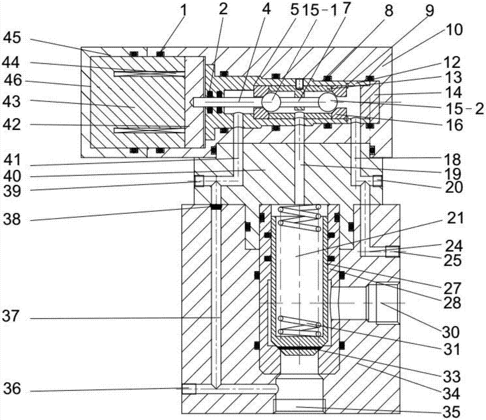
[0015] combine figure 1 , a high-pressure large-flow pneumatic electromagnetic switch valve is characterized in that it includes a housing, an electromagnet unit, a valve core unit, a valve sleeve unit, a valve body unit, a sealing plug 38, and a high-pressure gas inlet plug 39. The casing includes a pilot valve body 10 , an electromagnet end cover 45 , a control cover plate 40 and a main valve 34 . Among them, the control cover plate 40 is connected to the pilot valve body 10 and the main valve 34; the valve sleeve cavity 8 is set in the pilot valve body 10, and a groove body is set on the left side of the valve sleeve cavity 8, and the electromagnet end cover 45 is fixed on the pilot valve body 10 The left side cooperates with this tank body to form an electromagnet chamber 46; the control chamber 21 is set in the main valve 34, and an air inlet 35 and an exhaust port 30 are also arranged on the main valve 34, and the air inlet 35 connects the gas cylinder and connects the p...


PUM


Abstract

The invention provides a high pressure and mass flow pneumatic electromagnetic switch valve. The high pressure and mass flow pneumatic electromagnetic switch valve is provided with two air inlet passages, two exhaust passages, an electromagnet unit, a valve sleeve unit, a valve body unit, and a valve core unit; the two air inlet passages are connected with gas cylinders of different pressures, andthe two exhaust passages are connected with the external environment; the valve body unit moves within the valve sleeve unit under the action of the electromagnet unit and gas pressure of the gas cylinders to periodically open and close the air inlet passages and the exhaust passages, so that gas in the gas cylinders enters into a pneumatic engine through a exhaust port.

Description

technical field [0001] The invention designs a high-pressure pneumatic control technology, in particular a high-pressure and large-flow pneumatic electromagnetic switch valve. Background technique [0002] Conventional pneumatic components on the market generally have a working pressure of about 1MPa and a small flow rate, while for high-pressure pneumatic engines, the gas pressure is generally above 5MPa, and the requirements for the response time and gas flow rate of the control components are relatively high. [0003] Generally speaking, the working pressure of pneumatic actuators is around 1MPa. For vehicle-mounted pneumatics, due to the limited power energy, the pressure of the gas tank is generally high, while the conventional pneumatic system is decompressed by a pressure reducing valve before the intake air. And the principle of the decompression method is throttling and decompression, and the energy loss is relatively large. The high-pressure multi-pneumatic engine...

Claims


Application Information

Patent Timeline
IPC IPC(8): F16K1/00F16K31/06F16K31/42
CPCF16K1/00F16K31/0655F16K31/0675F16K31/42
Inventor 丁廷哲潘孝斌周鑫
Owner NANJING UNIV OF SCI & TECH
Why Eureka
Try Eureka