Die cutting device for porous ultrathin single-sided adhesive tape

A single-sided adhesive and die-cutting technology, which is applied in metal processing and other directions, can solve the problems of increasing the workload of cleaning single-sided adhesive waste, increasing operation steps and workload, and reducing production efficiency, so as to improve product quality and avoid faults. Silk phenomenon, the effect of improving production efficiency

Pending Publication Date: 2018-04-06
上海昊佰智造精密电子股份有限公司
View PDF5 Cites 6 Cited by
  • Summary
  • Abstract
  • Description
  • Claims
  • Application Information

AI Technical Summary

Problems solved by technology

If there are too many round holes on the single-sided adhesive product, during the first punching process, the flat knife punching die is easy to punch out hairs and stick to the die, and the die needs to be cleaned regularly, which increases the operation steps and workload; and The round hole scraps punched by the flat knife punching die are stored in the punching knife hole of the lower die of the flat knife punching die, and the waste needs to be cleaned manually on a regular basis. Since a lot of round hole scraps are punched out in one punching process, there is a single punch in the mold. The cleaning workload of surface glue waste will be greatly increased
In addition, in order to ensure the accuracy and stability of punching, the punching speed should not be too fast. If the single-sided adhesive product is too large, the flat-knife punching die can only punch one single-sided adhesive product at a time, which greatly reduces the cost. Productivity

Method used


Image

  • Die cutting device for porous ultrathin single-sided adhesive tape
  • Die cutting device for porous ultrathin single-sided adhesive tape
  • Die cutting device for porous ultrathin single-sided adhesive tape

Examples


Embodiment

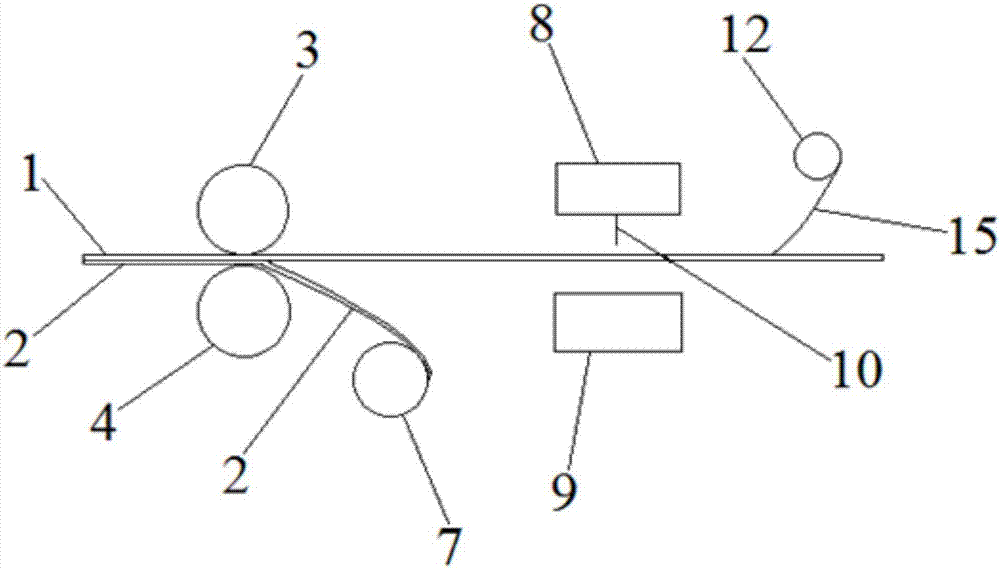
[0033] Such as figure 1 A die-cutting device for porous ultra-thin single-sided adhesive is shown, which includes a first die-cutting unit and a second die-cutting unit arranged in sequence along the moving direction of the single-sided adhesive tape 1, and the single-sided adhesive The lower surface of the belt 1 is provided with a waste discharge adhesive tape 2, the first die-cutting unit includes a circular knife die-cutting mechanism and the first waste discharge mechanism arranged in sequence along the moving direction of the single-sided adhesive tape 1, and the second die-cutting unit includes a The moving direction of the single-sided rubber belt 1 is provided with a flat-knife die-cutting mechanism and a second waste discharge mechanism. After the single-sided rubber belt 1 is punched by the first die-cutting unit, it is punched in the second die-cutting unit. type.

[0034] Wherein, the circular-knife die-cutting mechanism includes a circular-knife die-cutting roll...


PUM


Abstract

The invention relates to a die cutting device for porous ultrathin single-sided adhesive tape. The die cutting device comprises a first die cutting unit and a second die cutting unit which are sequentially arranged in the moving direction of a single-sided adhesive tape material strap, and waste discharging adhesive tape is arranged on the lower surface of the single-sided adhesive tape material strap. The first die cutting unit comprises a circular knife die cutting mechanism and a first waste discharging mechanism which are sequentially arranged in the moving direction of the single-sided adhesive tape material strap, and the second die cutting unit comprises a flat knife die cutting mechanism and a second waste discharging mechanism which are sequentially arranged in the moving direction of the single-sided adhesive tape material strap. The single-sided adhesive tape material strap is perforated through the first die cutting unit and then subjected to punching forming in the seconddie cutting unit. Compared with the prior art, the die cutting device for the porous ultrathin single-sided adhesive tape is advantageous in that in the die cutting process of circular holes, a flat knife punching mode is changed into a circular knife punching mode, so that the broken filament phenomenon occurring during die cutting is effectively avoided, meanwhile, continuous and automatic wastedischarging is achieved, complicated steps of intermittent waste discharging at regular intervals are avoided, working efficiency is greatly improved, labor cost is lowered, the die cutting speed canbe changed, and product quality is good.

Description

technical field [0001] The invention belongs to the technical field of single-sided adhesive processing, and relates to a die-cutting device for porous ultra-thin single-sided adhesive. Background technique [0002] In the processing of single-sided adhesive tape, die-cutting process is often used. When die-cutting the single-sided adhesive, if the structure of the single-sided adhesive is more complicated, a multi-step die-cutting method will be used to process the single-sided adhesive into shape. For example, when there are many round holes on the single-sided adhesive product, a two-step punching process is generally used: (1) on the first punching die, punch the inside of the single-sided adhesive; (2) on the second punching die, Die-cut the outer contour of the single-sided adhesive to get the finished single-sided adhesive. [0003] In the existing punching process, the first punching die and the second punching die are both flat knife punching dies. If there are t...

Claims


Application Information

Patent Timeline
Patent Type & Authority Applications(China)
IPC IPC(8): B26D1/22B26D7/18B26F1/38
CPCB26D1/225B26D7/18B26F1/38
Inventor 邢海易小雷刘晓鹏
Owner 上海昊佰智造精密电子股份有限公司
Why Eureka
Try Eureka