Deviation correction method of scribing machine and scribing machine
A marking machine and deviation technology, applied in the field of track and field track and traffic road marking line marking machine, can solve the problems of low efficiency, low precision, high labor intensity, etc., achieve great engineering practical significance and improve the effect of automation
- Summary
- Abstract
- Description
- Claims
- Application Information
AI Technical Summary
Problems solved by technology
Method used
Image
Examples
Embodiment 1
[0028] A method for correcting the deviation of a marking machine provided by the present invention is as follows:
[0029] 1) Pre-draw a reference line on the track and field track or traffic road surface. The reference line is a slender straight line, and its color is better than the base color of the track and field track or traffic road surface;
[0030] 2) Obtain the position image of the reference line through the camera unit installed on the marking machine;
[0031] 3) It is preferable to read the picture captured by the camera at a speed of 5-10 frames per second, and use it as a reference;
[0032] 4) The left and right edge lines of the screen are used as the left and right judgment lines, and the control unit extracts the continuous lines with obvious color differences in the screen through image processing as the baseline;
[0033] 4) When the distance from the reference line to the left and right judgment lines is equal, it is judged that the position of the mar...
Embodiment 2
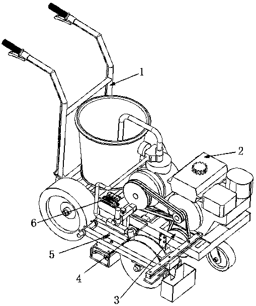
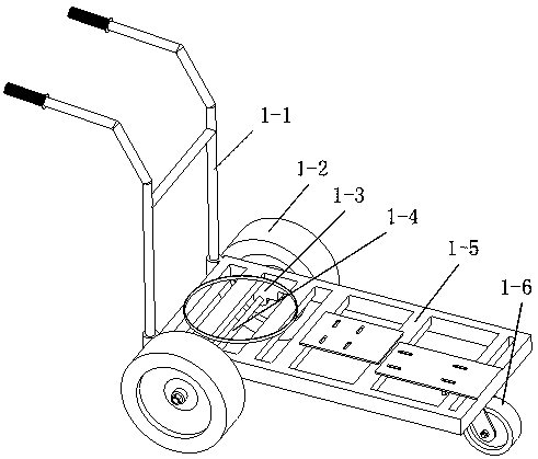
[0037] Such as Figure 1-5 As mentioned above, a marking machine of the present invention includes a frame unit 1 and a power unit 3 installed on the frame unit 1 , a power supply unit 3 , a spraying unit 4 , a position correction unit 5 and a control unit 6 . The power unit is located in front of the frame unit, the power supply unit is located below the frame unit, the spraying unit is located on the right side of the frame unit, the position correction unit is located below the frame unit, and the control unit is located above the frame unit.
[0038] The position correction unit 5 includes a camera unit 5-1, a first drive motor 5-4, a drive slide 5-2, and a shaft coupling 5-3, and the camera unit 5-1 is installed on the bottom of the frame unit 1 for In order to obtain the position image of the reference line, the control unit 6 obtains the position of the reference line by image processing the acquired image, and when the control unit 6 judges that the position of the mar...
PUM
 Abstract
Description
Claims
Application Information
 - R&D
- Intellectual Property
- Life Sciences
- Materials
- Tech Scout
- Unparalleled Data Quality
- Higher Quality Content
- 60% Fewer Hallucinations
Browse by: Latest US Patents, China's latest patents, Technical Efficacy Thesaurus, Application Domain, Technology Topic, Popular Technical Reports.
© 2025 PatSnap. All rights reserved.Legal|Privacy policy|Modern Slavery Act Transparency Statement|Sitemap|About US| Contact US: help@patsnap.com


