Polar group automatic continuous film coating system

A kind of pole group, coating technology, applied in the field of pole group automatic continuous coating system, can solve the problems of inability to realize pole group batch automatic coating, low pole group coating efficiency, poor coating effect and other problems, to achieve saving The effect of manpower, simple structure and high production efficiency

Inactive Publication Date: 2018-04-03
阜阳洁平日化有限公司
View PDF1 Cites 0 Cited by
  • Summary
  • Abstract
  • Description
  • Claims
  • Application Information

AI Technical Summary

Problems solved by technology

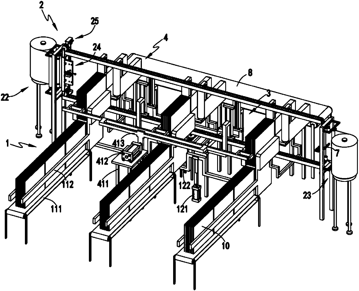
[0008] The purpose of the present invention is to address the deficiencies of the prior art, by setting a guide mechanism and setting two unwinding mechanisms at its two ends, and then absorbing and fixing the end of the film on the unwinding mechanism through the adsorption mechanism and then pulling Driven by the mechanism, the film is alternately unfolded, and the unfolded film is cut into equal parts by the cutting mechanism, and then the cut equal film is wrapped on several pole groups in cooperation with the advancing mechanism and the covering mechanism. Furthermore, it overcomes the problems that it is impossible to realize the batch automatic coating of the extreme group, the efficiency of the extreme group coating is low, it is labor-intensive and the coating effect is poor

Method used


Image

  • Polar group automatic continuous film coating system
  • Polar group automatic continuous film coating system
  • Polar group automatic continuous film coating system

Examples


Embodiment 1

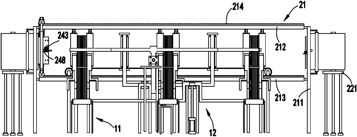
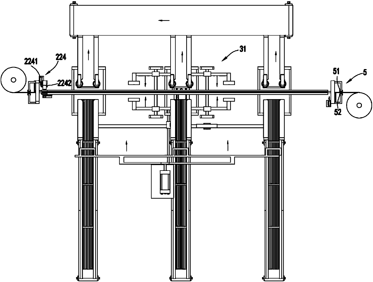
[0053] Such as figure 1 , figure 2 , image 3 , Figure 4 , Figure 5 , Image 6 , Figure 7 , Figure 8 , Figure 9 As shown, an automatic continuous coating system for pole groups includes a feeding device 1, and the feeding device 1 includes a horizontal conveying mechanism 11 for horizontally and continuously conveying the pole groups 10 and a lifting mechanism for lifting the pole groups 10. Agency 12;

[0054] Film unwinding device 2, described film unwinding device 2 comprises guiding mechanism 21, the first unwinding mechanism 22 and the second unwinding mechanism 23 that are respectively arranged on guiding mechanism 21 two ends, are used for first unwinding mechanism 22 and The end of the roll film on the second unwinding mechanism 23 is adsorbed and fixed by adsorption mechanism 24 and the traction mechanism 25 for driving the adsorption mechanism 24 and the end of the film to move along the guide mechanism 21;

[0055] Cutting device 3, described cutting ...

Embodiment approach

[0060] Further, as image 3 , Figure 4 with Figure 7 As shown, as a preferred embodiment, the guide mechanism 21 includes a fixed frame 211, a guide piece a212 and a guide piece b213 arranged in parallel up and down and fixed on the fixed frame 211, the guide piece a212 and the guide piece b213 The upper surface is provided with a rack a214 along its length direction;

[0061] The first unwinding mechanism 22 and the second unwinding mechanism 23 both include an unwinding frame 221, a support roller 222 fixed on the fixed frame 211, an upper limit roller 223 and a lower limit roller 223 respectively arranged on one side of both ends of the support roller 222. The positioning roller 224 and the cross-cut assembly 224 arranged on one side of the upper limiting roller 223 and the lower limiting roller 224, the upper limiting roller 223 and the lower limiting roller 224 are used to cooperate with the support roller 222 to adjust the upper and lower sides of the roll film Carr...

Embodiment 2

[0079] Such as figure 1 , figure 2 , image 3 , Figure 4 , Figure 5 , Image 6 , Figure 7 , Figure 8 , Figure 9 As shown, the parts that are the same as or corresponding to those in the first embodiment are marked with the corresponding reference numerals in the first embodiment. For the sake of simplicity, only the differences from the first embodiment will be described below. The difference between the second embodiment and the first embodiment is that further, the cutting mechanism 31 includes a sliding seat 311, a cutting assembly a312 and a cutting assembly b313 which are slidably arranged on the sliding seat 311 and symmetrically arranged front and rear;

[0080] The cutting assembly a312 includes a slider a3121 that cooperates with the guide rod b3111 on the sliding seat 311 to slide, a connecting frame a3122 that is fixedly connected with the sliding block a3121, a mounting frame a3123 that is arranged at the end of the connecting frame a3122, along the ve...


PUM


Abstract

The invention relates to a polar group automatic continuous film coating system. The polar group automatic continuous film coating system comprises a feeding device, a thin film unreeling device, a slitting device and a coating device, wherein the feeding device comprises a horizontal conveying mechanism and a lifting mechanism. The thin film unreeling device comprises a guide mechanism, a first unreeling mechanism, a second unreeling mechanism, an absorption mechanism and a transaction mechanism, wherein the first unreeling mechanism and the second unreeling mechanism are arranged at the twoends of the guide mechanism, the adsorption mechanism is used for adsorbing and fixing the end part of thin films on the unreeling mechanism, and the traction mechanism is used for driving the adsorption mechanism and the end part of the thin films to move along the guide mechanism. The slitting device comprises a cutting mechanism and a driving mechanism, wherein the cutting mechanism and the driving mechanism are arranged on the front side and the rear side of the guide mechanism, the cutting mechanism is driven by the driving mechanism to cut unfolded thin films at equal intervals, and theends of the thin films are limited after cutting is completed. The coating device comprises a pushing mechanism and a coating mechanism, wherein the pushing mechanism is used for pushing a polar group to move in the horizontal direction and is matched with the coating mechanism to finish coating of the polar group. The polar group automatic continuous film coating system solves the problems thatpolar group batch automatic film coating cannot be realized, the film coating efficiency is low, the labor is consumed, and the film coating effect is poor.

Description

technical field [0001] The invention relates to the technical field of lead-acid battery pole group coating equipment, in particular to a pole group automatic continuous coating system. Background technique [0002] The operation method of the traditional battery stacker is likely to cause quality problems such as diaphragms or pole plates in the package, uneven heights, and dust accumulation on the platform, which not only affects the work efficiency, but also affects the quality of the battery. Due to the occurrence of the two important quality unqualified items of internal electrode plate false welding and short circuit, a layer of film will be wrapped on the electrode group. In the battery industry, the coating operation of the electrode group is generally adopted on a simple platform and completely relies on manual labor. For encapsulation, the necessary tools are lacking. [0003] Authorized notification number CN201520895976.X is a Chinese utility model patent, which...

Claims


Application Information

Patent Timeline
Patent Type & Authority Applications(China)
IPC IPC(8): B65H16/00B65H35/02H01M10/12
CPCB65H16/00B65H35/02H01M10/12Y02E60/10Y02P70/50
Inventor 郭长杰
Owner 阜阳洁平日化有限公司
Why Eureka
Try Eureka