
Automatic stacking device for iron-core silicon-steel sheets of transformers

A technology of transformer iron core and stacking device, which is applied in the stacking of objects, de-stacking, transportation and packaging of objects, etc., can solve the problem of inability to adapt to the diversification of products by users, inability to automatically judge and identify, and affect the quality of transformer assembly. and other problems, to achieve the effect of saving stacking time, ensuring neatness and wide application

Pending Publication Date: 2018-04-03
南通睿驰智能科技有限公司
View PDF8 Cites 7 Cited by
  • Summary
  • Abstract
  • Description
  • Claims
  • Application Information

AI Technical Summary

Problems solved by technology

[0003] The existing technology has the following disadvantages when assembling transformers: ①The correctness of transformer assembly depends entirely on manual identification of incoming materials, which cannot be automatically judged and identified, and the assembly efficiency is low, and the qualified rate of products is low; The uniformity of incoming assembly materials is poor, which affects the assembly quality of transformers; ③The assembly line can only complete the assembly of silicon steel sheets of a single specification, which cannot meet the diverse needs of users for products

Method used


Image

  • Automatic stacking device for iron-core silicon-steel sheets of transformers
  • Automatic stacking device for iron-core silicon-steel sheets of transformers
  • Automatic stacking device for iron-core silicon-steel sheets of transformers

Examples


Embodiment Construction

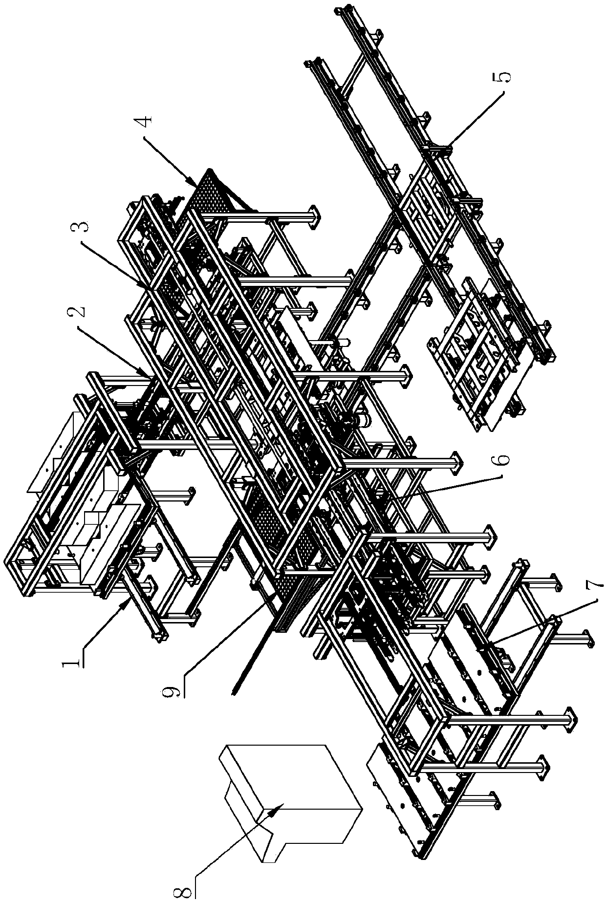
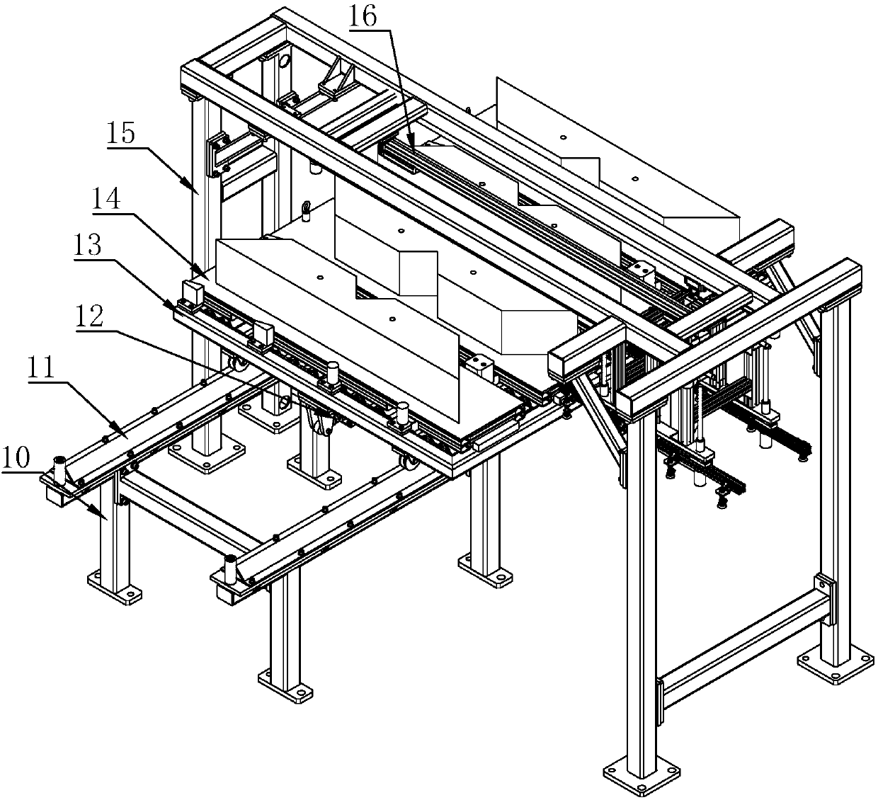
[0032] Such as figure 1As shown, an automatic palletizing device for transformer iron core silicon steel sheets in the present invention includes a first bin mechanism 1, a first transmission mechanism 2, a palletizing mechanism 3, a charging mechanism 5, a second bin mechanism 7 and a second The transmission mechanism 6, the first bin mechanism 1 is used to store the upper and lower yoke type silicon steel sheets to be assembled, and the first transmission mechanism 2 is used to transport the upper and lower yoke type silicon steel sheets on the first bin mechanism 1 to the palletizing mechanism 3, the second bin mechanism 7 is used to store side-in-column silicon steel sheets to be assembled, and the second transmission mechanism 6 is used to transport the side-in-pillar silicon steel sheets on the second bin mechanism 7 to the palletizing mechanism Below 3, the upper and lower yoke-type silicon steel sheets and the side-center column-type silicon steel sheets are alternatel...


PUM


Abstract

The invention discloses an automatic stacking device for iron-core silicon-steel sheets of transformers. The automatic stacking device comprises a first stock bin mechanism, a first transmission mechanism, a stacking mechanism, a loading mechanism, a second stock bin mechanism and a second transmission mechanism, wherein the first stock bin mechanism is used for storing upper yoke-sheet silicon-steel sheets to be assembled and lower yoke-sheet silicon-steel sheets to be assembled; the first transmission mechanism is used for conveying the upper yoke-sheet silicon-steel sheets and the lower yoke-sheet silicon-steel sheets on the first stock bin mechanism to the space below the stacking mechanism; the second stock bin mechanism is used for storing side-column silicon-steel sheets to be assembled and central-column silicon-steel sheets to be assembled; the second transmission mechanism is used for conveying the side-column silicon-steel sheets and the central-column silicon-steel sheets on the second stock bin mechanism to the space below the stacking mechanism; and the upper yoke-sheet silicon-steel sheets, the lower yoke-sheet silicon-steel sheets, the side-column silicon-steel sheets and the central-column silicon-steel sheets are alternately stacked on the loading mechanism through the stacking mechanism according to the transformer specifications needed by customers. The automatic stacking device disclosed by the invention is high in assembly yield and capable of automatically identifying incoming materials, and the assembled products are diversified.

Description

technical field [0001] The invention relates to the technical field of transformer assembly, in particular to an automatic palletizing device for transformer iron core silicon steel sheets. Background technique [0002] With the continuous improvement of the degree of electrification, the demand for electric power is constantly increasing. As an important equipment in power transmission, the demand for transformers is self-evident, and the demand for small and medium-sized transformers is particularly prominent. The structure and performance of the iron core in the transformer directly affect the overall performance of the transformer, so the manufacturing process of the transformer iron core requires high precision. The existing transformer iron core is made of silicon steel sheets with a thickness of 0.27-0.3 mm, and finally stacked into a "day" shape. On average, a small and medium-sized transformer is composed of more than 5,000 silicon steel sheets. [0003] The exist...

Claims


Application Information

Patent Timeline
Patent Type & Authority Applications(China)
IPC IPC(8): B65G61/00B65G47/91
CPCB65G47/91B65G61/00
Inventor 刘超朱向阳周恩权张亚平盛鑫军
Owner 南通睿驰智能科技有限公司
Learn More