
Grain dryer automatic control device and control method thereof

An automatic control device and drying machine technology, applied in the direction of non-electric variable control, temperature control, control/regulation system, etc., can solve the problems of manpower consumption, high energy consumption of the dryer, inconvenient operation, etc., and achieve improved effect, Improve the level of automation and reduce the effect of human intervention

Inactive Publication Date: 2018-03-30
CHANGDE KEXIANG ELECTRICAL MFG
View PDF5 Cites 10 Cited by
  • Summary
  • Abstract
  • Description
  • Claims
  • Application Information

AI Technical Summary

Problems solved by technology

[0003] At present, the common drying equipment is the tower dryer. The existing tower dryer is equipped with relatively few automatic control devices, mainly manual operation, which cannot realize comprehensive mechanical automation, and requires more human operation, which is costly. At the same time, the dryer consumes a lot of energy and is inconvenient to operate
Man-made operation will inevitably result in unsatisfactory drying effect of the grain, which cannot meet the drying requirements. In addition, the cause and location of the failure cannot be clearly judged when the machine fails. The work efficiency of dry operation cannot meet the current increasing demand for grain production

Method used


Image

  • Grain dryer automatic control device and control method thereof
  • Grain dryer automatic control device and control method thereof
  • Grain dryer automatic control device and control method thereof

Examples


Embodiment Construction

[0024] The present application will be further explained below in combination with specific embodiments and accompanying drawings.

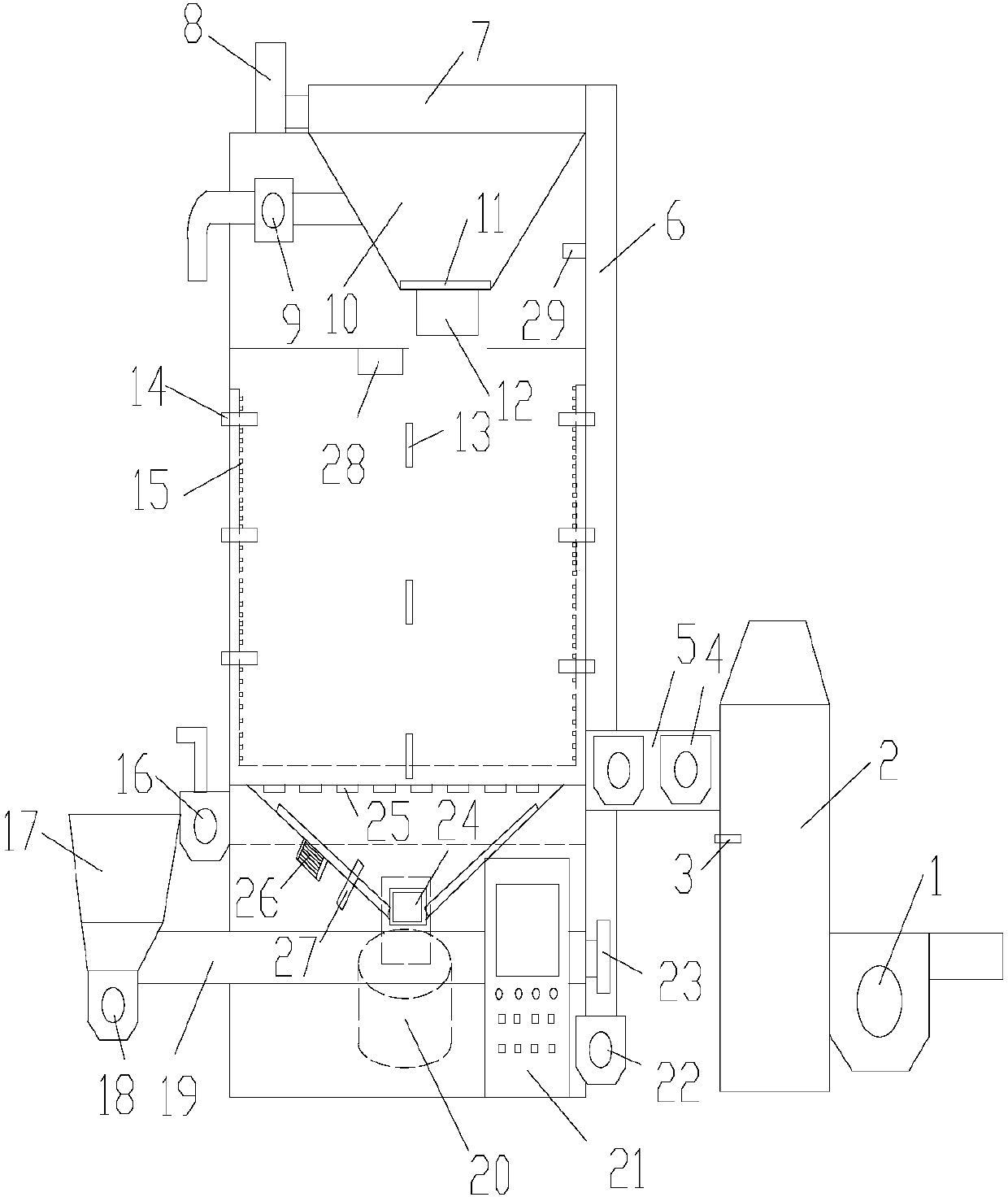
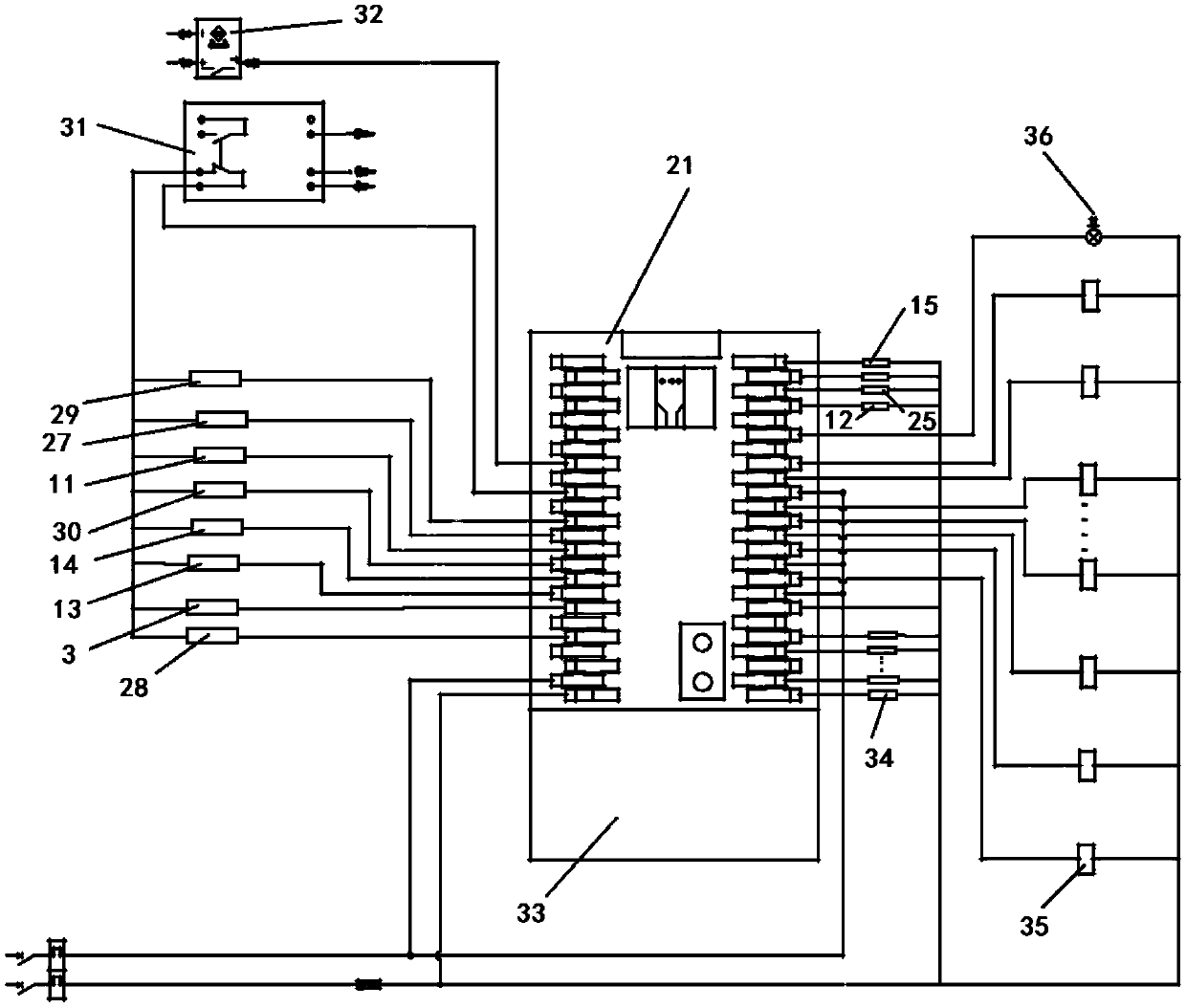
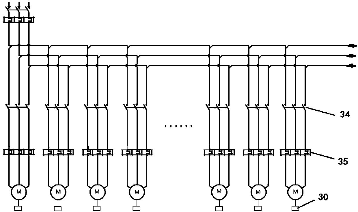
[0025] see figure 1 , the dryer includes a drying tower, the hot air channel of the drying tower is connected to the hot blast stove 2 through the hot air pipe 5, the hot air pipe 5 is provided with the induced draft motor 4, the hot blast stove 2 is connected to the blower motor 1, and the hot blast stove 2 A hot blast stove temperature sensor 3 is arranged on the top, an exhaust motor 16 is connected to the air outlet of the drying tower, an upper auger 7 is arranged on the top of the drying tower, and the upper auger 7 is connected to an upper auger motor 8, and the side wall of the drying tower A hoist 6 is provided, and a hoist motor 22 is arranged on the hoist 6. The bottom of the drying tower is provided with a lower auger 19, the lower auger 19 is connected to the lower auger motor 23, the top of the hoist 6 is connected to the upper auge...


PUM


Abstract

The application discloses a grain dryer automatic control device and a control method thereof. The technical scheme adopted is as follows: a PLC controls a lifting motor, an upper auger motor and a lower auger motor, and a grain discharging motor is started to transport the grains in a feeding hopper to a drying tower until the drying tower is full; and for drying, the hot air temperature in a hotblast stove, the temperature in the drying tower and the moisture content of the grains are set first according to the process requirements, a temperature sensor collects temperature information in real time and feeds back the temperature information to the PLC, the PLC controls the speeds of a blower motor, an induction motor and an exhaust motor according to the temperature information to fullyensure the effect of drying, a moisture meter collects the moisture change of the grains in real time until the moisture content drops to a set value, a discharging hopper is opened, a transport component motor is started, and the grains are transported out through a transport component. The level of automation of the drain drying process can be improved, human intervention can be reduced, and therefore, the grain drying effect is improved.

Description

technical field [0001] The present application relates to the field of automatic control of grain drying, in particular to an automatic control device for a grain dryer and a control method thereof. Background technique [0002] Grain is a necessity of human life. All countries attach great importance to grain production and storage. China is the world's largest grain producer and consumer. Grain is a living organism, and water is the condition for its survival. However, excessive moisture will induce the growth of insects and microorganisms, which will easily cause heat generation, fermentation, deterioration, and a decrease in germination rate of the grain. Therefore, the grain needs to be air-dried or dried to reduce the moisture content of the grain before being stored in the warehouse. Taking grain as an example, grain harvesting The moisture content at the time of storage is 25-30%, and it needs to be reduced to a safe moisture content of 13-15% as soon as possible dur...

Claims


Application Information

Patent Timeline
Patent Type & Authority Applications(China)
IPC IPC(8): G05D23/20A23B9/08
CPCG05D23/20A23B9/08
Inventor 夏誉文
Owner CHANGDE KEXIANG ELECTRICAL MFG
Learn More