Stirring device for producing concrete

A mixing device and concrete technology, which is applied in the direction of cement mixing device, clay preparation device, mixer accessories, etc., can solve the problem of single mixing method of mixture raw materials, achieve the effect of improving adaptability, reducing noise volume, and improving practicability

Inactive Publication Date: 2018-03-30
盐城市双强管桩有限公司
View PDF0 Cites 3 Cited by
  • Summary
  • Abstract
  • Description
  • Claims
  • Application Information

AI Technical Summary

Problems solved by technology

[0002] As we all know, the mixing device for concrete production is an auxiliary device used in the concrete production process to stir the mixture so that it can be used better, and it has been widely used in the field of concrete production; the existing The mixing device for concrete production includes a working box and four sets of brackets. The tops of the four sets of brackets are respectively installed on the left front side, right front side, left rear side and right rear side of the bottom of the working box. There is a working chamber in the working box, and the top of the working box is connected There is a pick-and-place opening, and a cover is set at the pick-and-place opening, and it also includes two sets of support columns, support plates, motors, first connecting rods, connecting columns, transmission shafts and stirring blades. The top ends of the two sets of support columns are respectively Installed on the left and right sides of the bottom of the work box, the bottom ends of the two sets of support columns are connected to the top of the support plate, the bottom of the motor is in contact with the top of the support plate, the bottom of the first connecting rod is connected to the output end of the top of the motor, and the bottom of the connection column The end is installed on the top of the first connecting rod, the top of the connecting column passes through the bottom side wall of the working box and extends into the inside of the working chamber, the bottom of the transmission shaft is connected to the top of the connecting column, the stirring blade is installed on the transmission shaft, and the lower sealing ring is also included. The lower sealing ring is located inside the working chamber, and the lower sealing ring is set on the outside of the connecting column, and the bottom of the lower sealing ring is close to the inner bottom and side wall of the working chamber; when the existing mixing device for concrete production is used, the mixture raw material is passed through the pick-up port They are all introduced into the working chamber, and the motor drives the stirring blade to rotate and stir evenly, and then it can be taken out through the pick-up and release port; it is found in the use of the existing mixing device for concrete production that the mixing method of the mixture raw material is relatively single, which leads to high limitations in use; And it can't conveniently observe the stirring situation inside the working chamber, resulting in poor practicability; and the noise volume generated when the motor is working is relatively large, resulting in low adaptability

Method used


Image

  • Stirring device for producing concrete
  • Stirring device for producing concrete
  • Stirring device for producing concrete

Examples


Embodiment Construction

[0016] The specific implementation manners of the present invention will be further described in detail below in conjunction with the accompanying drawings and embodiments. The following examples are used to illustrate the present invention, but are not intended to limit the scope of the present invention.

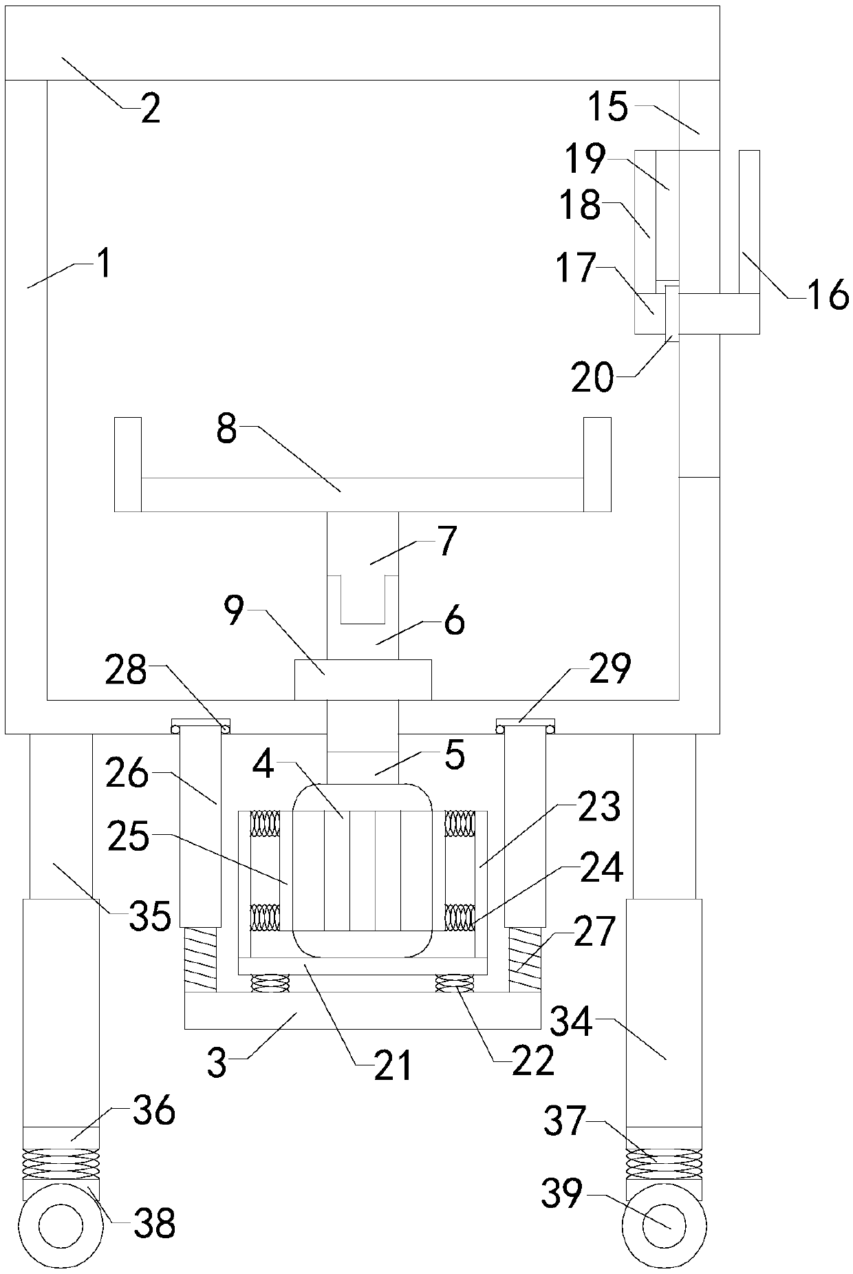
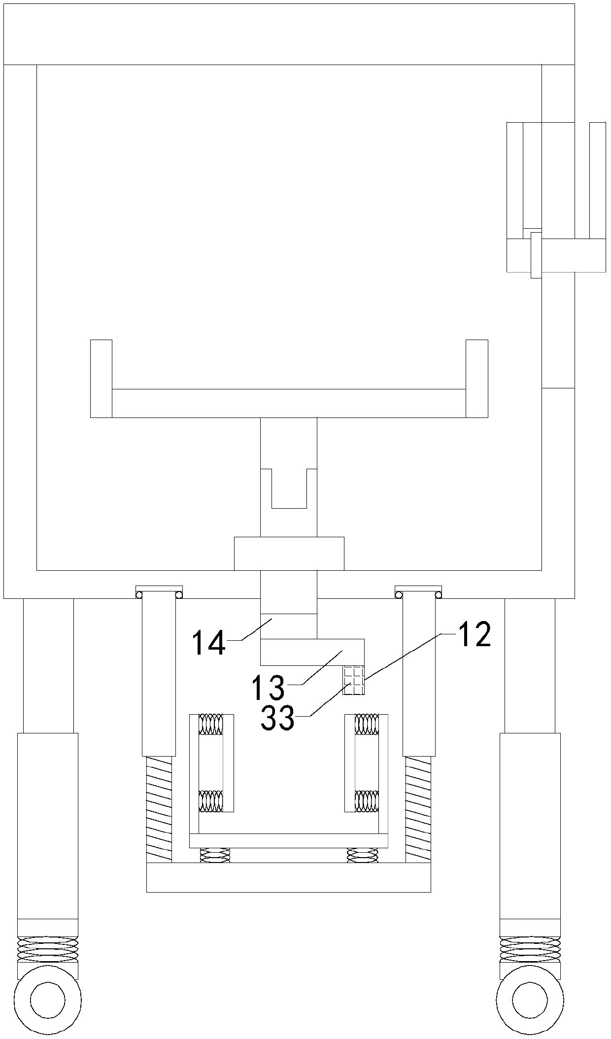
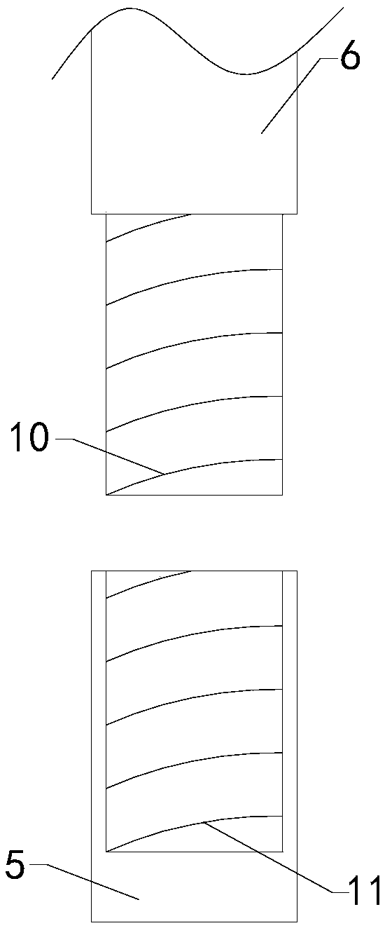
[0017] Such as Figure 1 to Figure 4 As shown, a mixing device for concrete production of the present invention includes a working box 1 and four sets of supports, a working chamber is arranged in the working box, a pick-and-place opening is arranged at the top of the work box, and a stopper is arranged at the pick-and-place mouth. The cover 2 also includes two sets of support columns, a support plate 3, a motor 4, a first connecting rod 5, a connecting column 6, a transmission shaft 7 and a stirring blade 8, the bottom end of the first connecting rod is connected to the output end of the top of the motor, and the connecting column The top end passes through the bottom si...


PUM


Abstract

The invention relates to the technical field of concrete stirring accessory devices and particularly relates to a stirring device for producing concrete; various mixture raw material stirring methodsare provided; the usage limitation of the stirring device is reduced; the stirring condition in an operation chamber can be conveniently observed, so that the practicability of the stirring device isimproved; the noise volume generated by a motor during operation is reduced, so that the adaptability of the stirring device is improved. The stirring device comprises an operation box and four groupsof support frames, wherein an operation chamber is formed in the operation box; the top end of the operation box is connected with a taking and placing opening; a blocking cover is arranged at the taking and placing opening; the stirring device also comprises two groups of support pillars, a support plate, a motor, a first connection rod, a connection pillar, a transmission shaft and a stirring blade; the stirring device further comprises a handle, a connection plate and a second connection rod; an observation hole is formed in the side wall of the operation box and is connected with the sidewall of the operation box; a transparent baffle is arranged at the observation hole; the stirring device also comprises a rotating handle, a rotating shaft, a driving shaft, a scraping plate, an upper sealing ring, a support platform, a connection spring set, two groups of fixing plates, two groups of clamping springs and two groups of clamping plates.

Description

technical field [0001] The invention relates to the technical field of concrete mixing attachments, in particular to a mixing device for concrete production. Background technique [0002] As we all know, the mixing device for concrete production is an auxiliary device used in the concrete production process to stir the mixture so that it can be used better, and it has been widely used in the field of concrete production; the existing The mixing device for concrete production includes a working box and four sets of brackets. The tops of the four sets of brackets are respectively installed on the left front side, right front side, left rear side and right rear side of the bottom of the working box. There is a working chamber in the working box, and the top of the working box is connected There is a pick-and-place opening, and a cover is set at the pick-and-place opening, and it also includes two sets of support columns, support plates, motors, first connecting rods, connecting...

Claims


Application Information

Patent Timeline
Patent Type & Authority Applications(China)
IPC IPC(8): B28C5/16B28C5/08B28C5/44B01F15/00
CPCB28C5/0806B28C5/0856B28C5/16B28C5/44B01F35/123
Inventor 凌德祥李光明邵淑敏凌慧
Owner 盐城市双强管桩有限公司
Why Eureka
Try Eureka