
Movable type screw locking tool

A screw locking and mobile technology, which is applied in the field of mobile screw locking tooling, can solve the problems of many operators, high labor costs, and high technical requirements for operators, and achieve the effects of ensuring product quality, saving labor costs, and high operating accuracy

Pending Publication Date: 2018-03-30
苏州弘瀚自动化科技有限公司
View PDF0 Cites 4 Cited by
  • Summary
  • Abstract
  • Description
  • Claims
  • Application Information

AI Technical Summary

Problems solved by technology

The disadvantage of the hand-held screw locking machine is that it requires more operators and it is easy to scratch the appearance of the product
Disadvantages of the fully automatic screw locking machine are poor compatibility. When replacing products, it takes a long time to adjust and requires high technical requirements for the operator. The position data of the screw holes is exported by the engineer from the CAD file of the product shell, and imported by the engineer into the automatic lock. The screw machine can be locked after programming and optimization. On the one hand, high-quality operators are required. On the other hand, the pre-processing takes up a lot of time.
In short, the main problem of the existing screw locking technology is that the precise screw hole position cannot be obtained quickly and effectively, the preparatory work for locking the screw takes a long time, and the labor cost is relatively high.

Method used


Image

  • Movable type screw locking tool
  • Movable type screw locking tool

Examples


Embodiment Construction

[0013] The present invention will be further described below in conjunction with the accompanying drawings and specific embodiments, so that those skilled in the art can better understand the present invention and implement it, but the examples given are not intended to limit the present invention.

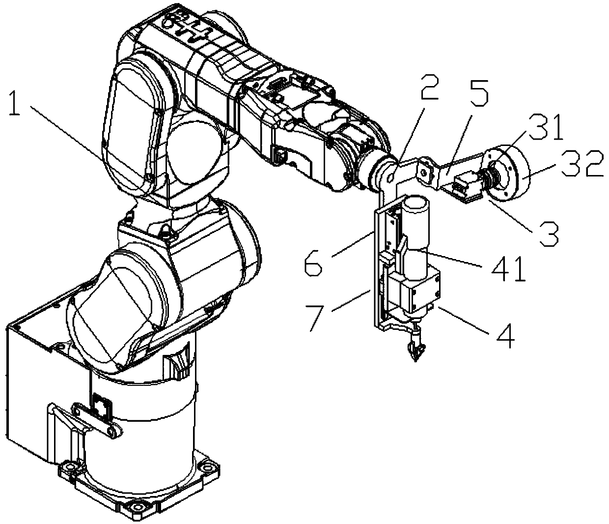
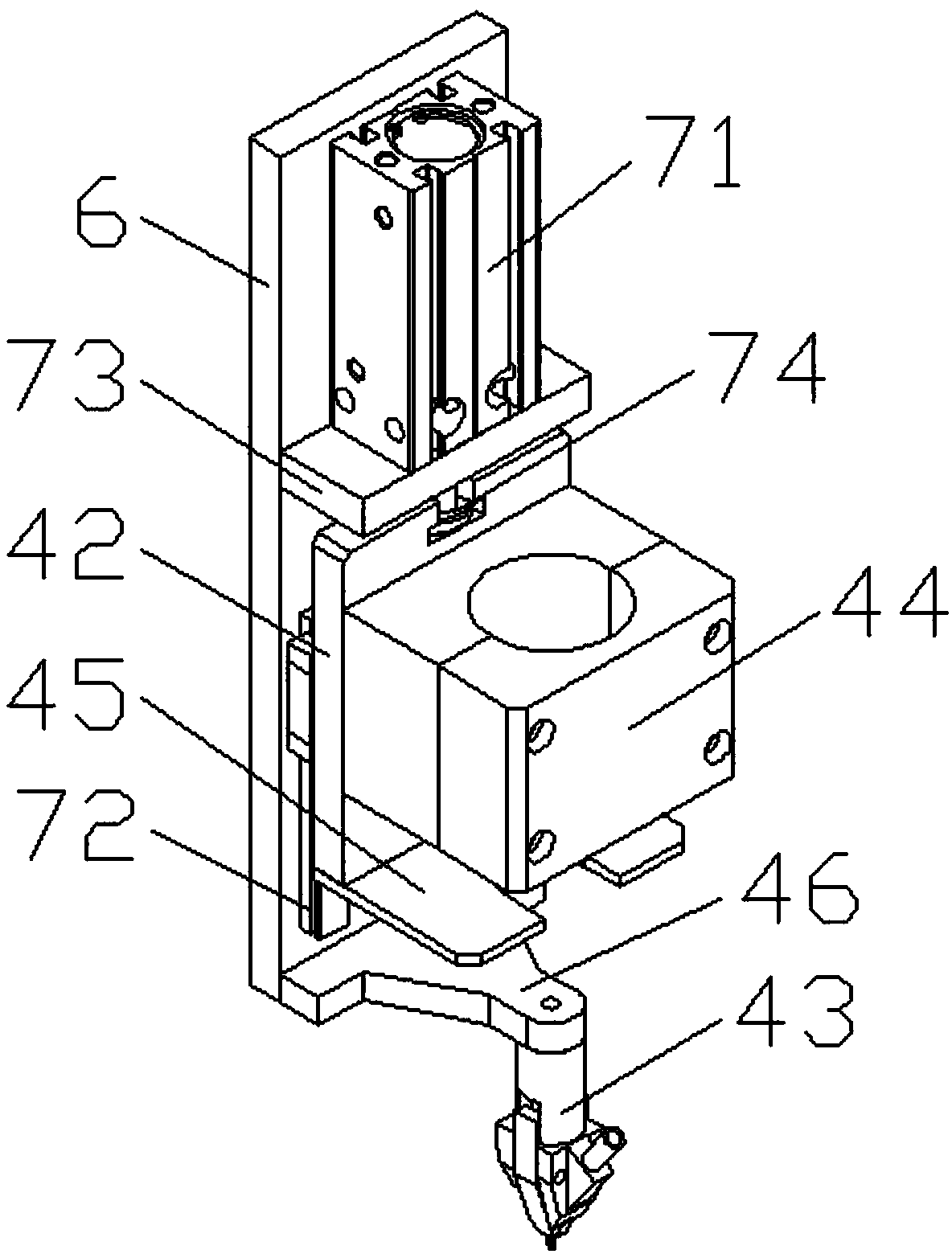
[0014] Such as figure 1 , figure 2 As shown, a mobile locking screw tooling includes a mechanical arm 1, a bracket 2 installed on the end of the mechanical arm 1, a positioning mechanism 3 and a locking screw mechanism 4 fixed on the bracket 2, the positioning mechanism 3 and the locking screw mechanism 4 is installed at a certain angle on the bracket 2. The positioning mechanism 3 is used to scan the workpiece and determine the position of the screw hole. The locking screw mechanism 4 is used to introduce and tighten the screws. The positioning mechanism 3 is fixed to the bracket 2 through the positioning plate 5. The positioning mechanism 3 Including a camera 31 and a light so...


PUM


Abstract

The invention discloses a movable type screw locking tool. The movable type screw locking tool comprises a mechanical arm, a bracket mounted on the mechanical arm, a positioning mechanism and a screwlocking mechanism which are fixed on the bracket, wherein the positioning mechanism and the screw locking mechanism are mounted on the bracket at a certain angle; the positioning mechanism is used forscanning a workpiece and determining the position of a screw hole; the screw locking mechanism is used for enabling a screw to be guided in and tightened; the positioning mechanism is fixed with thebracket through a positioning plate; the screw locking mechanism is fixed with the bracket through a back plate; and a moving mechanism is further arranged between the screw locking mechanism and theback plate. The movable type screw locking tool has the benefits as follows: the mechanical arm can hold the positioning mechanism to carry out the scanning work, so that the screw hole can be detected quickly and effectively, the machine does not need to be regulated, the application range is wide, the operation precision of the mechanical arm is high, the product quality is ensured, the result can also be detected again by utilizing the positioning mechanism after the completion of positioning, the working efficiency is high, and the labor cost is saved.

Description

technical field [0001] The invention relates to the field of screw locking devices, in particular to a mobile screw locking tool. Background technique [0002] In the current industrial production, assembly is an important process, and it is also the process that requires the most personnel. Nowadays, with the development of the economy, manpower is scarce and labor costs are increasing. In order to improve economic benefits, the factory reduces the number of employees, especially the number of technical engineers. Dependence on human resources has been put on the agenda, and it has become a current trend for machines to replace personnel for product assembly. In the final stage of product assembly, the screws on the shell are usually locked, but the screw locking devices on the market are handheld automatic screw locking machines and fully automatic screw locking machines. The disadvantage of the hand-held screw locking machine is that it requires more operators and it is ...

Claims


Application Information

Patent Timeline
IPC IPC(8): B23P19/06
CPCB23P19/007B23P19/06
Inventor 陈信宏
Owner 苏州弘瀚自动化科技有限公司
Learn More