Image-reading device
An image reading device and an image reading technology, which are applied in the directions of printing devices, image communication, electric recording process applying charge patterns, etc. Effect
- Summary
- Abstract
- Description
- Claims
- Application Information
AI Technical Summary
Problems solved by technology
Method used
Image

Examples
Embodiment approach 1
[0030] Hereinafter, embodiments of the present invention will be described in detail based on the drawings. In addition, the present invention is not limited to the following embodiments.
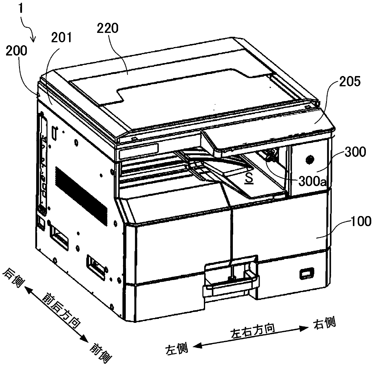
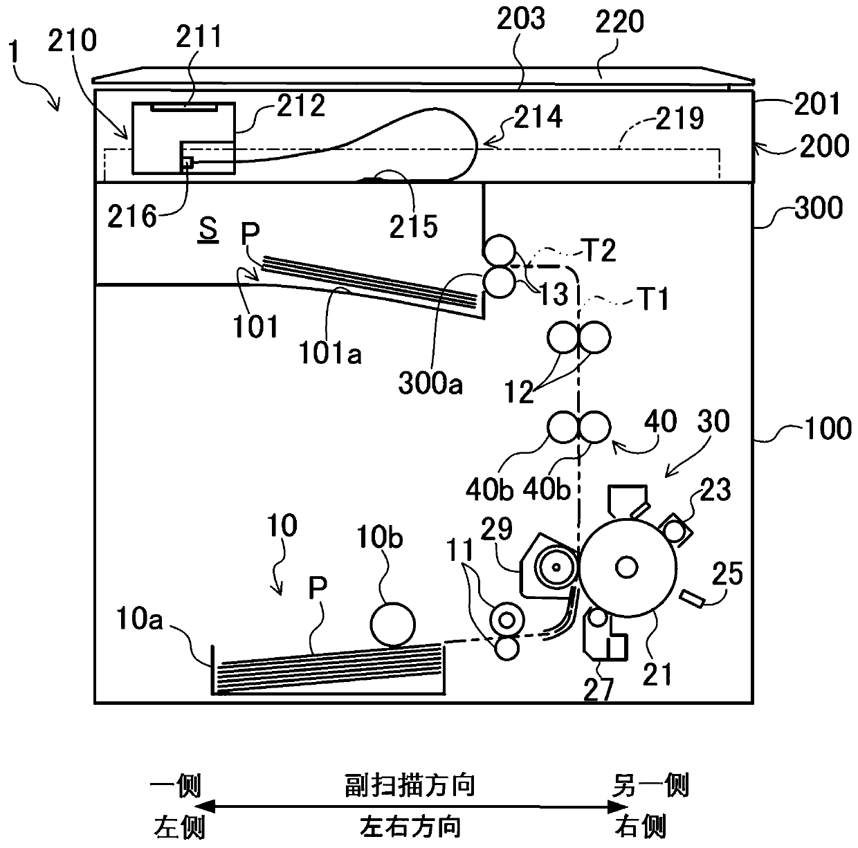
[0031] figure 1 The image forming apparatus 1 including the image reading apparatus 200 according to the present embodiment is shown. The image forming apparatus 1 is a so-called internal discharge machine, and includes an image forming apparatus main body 100 , an image reading device 200 , and a supporting case unit 300 . The image reading device 200 reads a document image and acquires the image data. The image data acquired by the image reading device 200 is printed on paper P in the image forming apparatus main body 100 . The image reading device 200 is supported on the upper side of the image forming device main body 100 via the supporting case portion 300 . A paper discharge space S is formed between the image forming apparatus main body 100 and the image reading apparatus 200 . ...
Embodiment approach 2
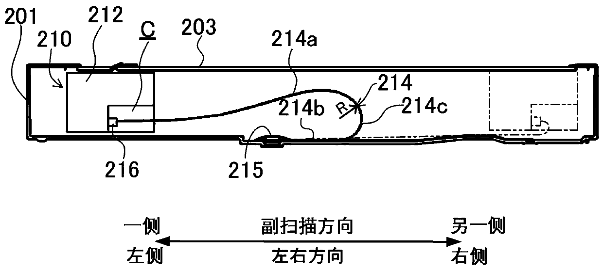
[0051] Figure 8 Embodiment 2 is shown. This second embodiment differs from the above-mentioned first embodiment and the modified example in that the angle restricting portion for restricting the angle of the flat cable 214 is formed by the connector 216 itself.
[0052] That is, in Embodiment 2, the connector 216 is inclined toward one side and upward from the other side in the main scanning direction. According to this configuration, the upper side wall portion 214 a of the flat cable 214 connected to the connector 216 is inclined upward from one side in the main scanning direction toward the other side. Therefore, when the radius of curvature R of the curved portion 214c of the flat cable 214 increases during the movement of the carriage and the upper side wall portion 214a of the flat cable 214 comes into contact with the platen glass 203, the contact portion between the two can be moved toward the platen glass 203. One side in the main scanning direction of the flat cab...
Embodiment approach 3
[0054] Figure 9 Embodiment 3 is shown. This third embodiment differs from the above-described embodiments and modifications in that the angle restricting portion for restricting the angle of the flat cable 214 is formed by the insertion hole 212d itself.
[0055] That is, in the present embodiment, a rectangular parallelepiped-shaped notch C2 that opens toward the lower side and one side in the main scanning direction is formed at the lower end portion of the bracket 212 . Of the four side wall portions forming the notch portion C2 , the connector 216 protrudes from the wall surface facing the other side in the sub-scanning direction. A slit-shaped insertion hole 212d through which the upper wall portion 214a of the flat cable 214 is inserted is formed in the vertical wall portion 212c facing the connector 216 . The insertion hole 212d is inclined from the other side in the main scanning direction toward one side to the upper side. Therefore, the upper side wall portion 21...
PUM
 Abstract
Description
Claims
Application Information
 - R&D
- Intellectual Property
- Life Sciences
- Materials
- Tech Scout
- Unparalleled Data Quality
- Higher Quality Content
- 60% Fewer Hallucinations
Browse by: Latest US Patents, China's latest patents, Technical Efficacy Thesaurus, Application Domain, Technology Topic, Popular Technical Reports.
© 2025 PatSnap. All rights reserved.Legal|Privacy policy|Modern Slavery Act Transparency Statement|Sitemap|About US| Contact US: help@patsnap.com