Vehicle drive device

A technology for driving devices and vehicles, which is applied to transmission devices, electrical devices, power devices, etc., can solve problems such as temperature rise, inability to obtain driving torque, and inability of vehicles to drive, and achieve the effect of improving durability.

Inactive Publication Date: 2018-03-27
TOYOTA JIDOSHA KK
View PDF8 Cites 1 Cited by
  • Summary
  • Abstract
  • Description
  • Claims
  • Application Information

AI Technical Summary

Problems solved by technology

Therefore, part of the power output by the motor is consumed as frictional heat of the engagement mechanism.
In this way, when friction is generated in the engagement mechanism that should avoid so-called single-phase locking and the motor is rotated, there is a concern that the temperature of the engagement mechanism will increase due to frictional heat. Decreased durability
In order to suppress the deterioration of the durability of the engagement mechanism, it is only necessary to reduce the friction of the engagement mechanism, but if the friction is reduced, the rotation speed of the motor may not be increased to sufficiently suppress single-phase locking, or the engagement mechanism may be close to release state and cannot obtain sufficient driving torque, so that the vehicle cannot drive, etc.
Furthermore, even in the driving device described in Japanese Patent Application Laid-Open No. 2011-231857, the motor generator is used as the driving force source, but the possibility of single-phase locking of the motor generator or the possibility of avoiding single-phase locking The method and the like have not been disclosed in Japanese Patent Application Laid-Open No. 2011-231857

Method used


Image

  • Vehicle drive device
  • Vehicle drive device
  • Vehicle drive device

Examples


Embodiment Construction

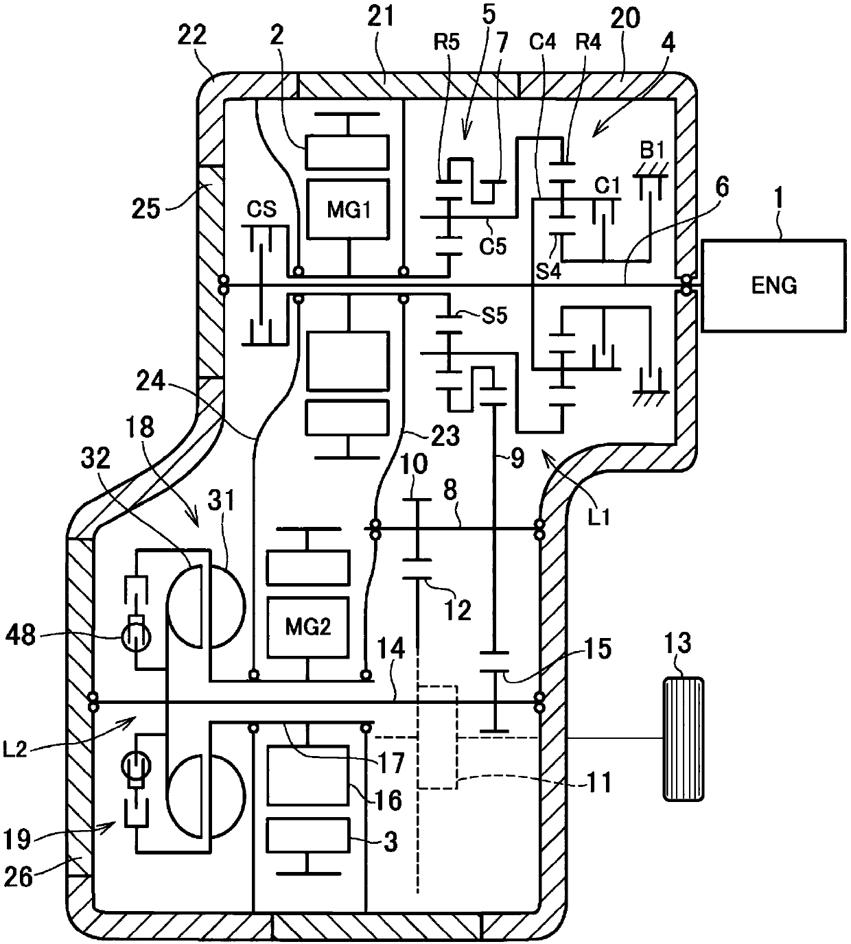
[0033] exist figure 1 An example of an embodiment of the present invention is shown by way of a block diagram in . The example shown here is an example in which the present invention is applied to a so-called dual-motor hybrid drive. An engine 1 and two electric motors 2 and 3 are provided as driving force sources. The electric motor 2 corresponds to another rotating electric machine in the embodiment of the present invention. In addition, the electric motor 3 corresponds to the rotating electric machine in the embodiment of the present invention. The engine (ENG) 1 is an internal combustion engine such as a gasoline engine or a diesel engine, and motor generators (MG1, MG2) having a power generation function such as permanent magnet three-phase synchronous motors can be used as the electric motors 2 and 3 .

[0034] On the same axis as the rotation center axis of the engine 1 , an overdrive mechanism 4 , a power split mechanism 5 , and a first motor generator ( MG1 ) 2 are...


PUM


Abstract

The purpose of the present invention is to provide a vehicle drive device that prevents, without loss of durability, a motor from entering a single-phase lock state, the motor serving as a drive powersource. Provided is a vehicle drive device comprising a first power transmission path (L1) for transmitting drive force output by an engine (1) to a drive wheel (13) and a second power transmission path (L2) for transmitting drive force output by a motor (3) to the drive wheel (13), wherein: the second power transmission path (L2) includes an intermediate shaft (14) for transmitting drive force output by the motor (3) to the first transmission path (L1); a fluid joint (18) is provided between the motor (3) and the intermediate shaft (14); and a clutch mechanism (19) is provided between the motor (3) and the intermediate shaft (14) in parallel with the fluid joint (18).

Description

technical field [0001] The present invention relates to a drive device for a vehicle including at least one electric motor in a drive power source. Background technique [0002] Japanese Patent Application Laid-Open No. 2006-256560 describes a power output device configured to connect an electric motor as a driving force source to a transmission, and to drive left and right from the transmission via a differential gear. wheel output torque. When the motor stops or is about to rotate at a low rotational speed and outputs a large driving force, a large current may flow to any specific one-phase coil among the plurality of coils, and overheating may occur. Such a state is sometimes called single-phase lock. In the device described in Japanese Patent Application Laid-Open No. 2006-256560, in order to avoid single-phase lock, a predetermined engagement mechanism such as a brake in the transmission is controlled to be in a sliding state, and The motor is controlled so as to obta...

Claims


Application Information

Patent Timeline
Patent Type & Authority Applications(China)
IPC IPC(8): B60K6/445B60K6/20B60L50/16
CPCB60K6/26B60K6/38B60K6/405B60W10/026B60W30/1843B60W2510/087B60W2710/024B60Y2400/426B60W20/50B60K6/445B60K6/365B60W10/08Y02T10/62Y02T10/72Y02T10/70Y02T10/7072B60K6/48B60L3/003B60L2240/36B60Y2200/92F16H2045/0252
Inventor 今村达也田端淳奥田弘一今井惠太
Owner TOYOTA JIDOSHA KK
Why Eureka
Try Eureka