
Lock

A lock and lock cylinder technology, applied in the field of locks, can solve the problems of poor anti-theft performance, simple structure of blade components, etc.

Pending Publication Date: 2018-03-27
ZHEJIANG HONGTAI ELECTRONICS EQUIP
View PDF5 Cites 0 Cited by
  • Summary
  • Abstract
  • Description
  • Claims
  • Application Information

AI Technical Summary

Problems solved by technology

[0002] The lock generally includes a lock cylinder, a key and a fixed sleeve. The lock cylinder is rotated and arranged in the fixed sleeve. The lock cylinder is provided with a key channel for the key to be inserted along its axial direction. blade assembly, so that only the correct key can be inserted into the key channel, but because the structure of the existing blade assembly is too simple, criminals can easily imitate the corresponding key, and the anti-theft performance is poor

Method used


Image

  • Lock
  • Lock
  • Lock

Examples


Embodiment Construction

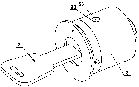
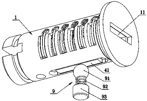
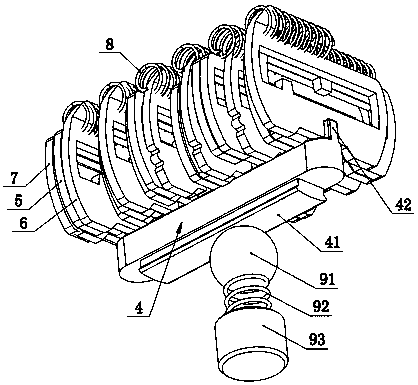
[0016] Such as Figure 1-7 Shown is a lock, including a lock core 1, a key 2 and a fixed sleeve 3, the lock core 1 is rotatably arranged in the fixed sleeve 3, and the lock core 1 is provided with a key passage for the key 2 to be inserted along its axial direction 11. A radial groove 12 is also provided on the lock cylinder 1, and a limit key 4 is radially inserted in the radial groove 12, and a radially outer end of the limit key 4 is provided with a protrusion 41, which is fixed The inner wall of the cover 3 is correspondingly provided with a limit groove 31 for the insertion of the protrusion 41, and a plurality of blade slots 13 are arranged linearly along the insertion direction of the key 2 on the lock cylinder 1, and each blade slot 13 are respectively connected with the key channel 11 and the radial groove 12, and each blade slot 13 is inserted with a starting blade 5, a front delay blade 6 and a rear delay blade 7, and the starting blade 5 is sandwiched Between the ...


PUM


Abstract

The invention discloses a lock. The lock comprises a lock cylinder, a key and a fixing sleeve, wherein the lock cylinder is rotationally arranged in the fixing sleeve; a key channel for allowing the key to be inserted in the axial direction is formed in the lock cylinder; a plurality of blade insertion grooves are formed in the lock cylinder in a linear arrangement manner in the insertion direction of the key; each blade inserting groove is internally provided with a starting blade, a front time delay blade and a rear time delay blade in an inserted mode; each starting blade is clamped betweenthe corresponding front time delay blade and the corresponding rear time delay blade; a first core block which extends into the key channel is correspondingly arranged on each starting blade; a second core block which extends into the key channel is correspondingly arranged on each front time delay blade; a third core block which extends into the key channel is correspondingly arranged on each rear time delay blade; the first core blocks are correspondingly arranged on one side of the key channel; the second core blocks and the third core blocks are correspondingly arranged on the other sideof the key channel; and each first core block and the corresponding second core block and the corresponding third core block are arranged in a delta-shaped manner. The structure is adopted, and the lock is better in anti-theft performance.

Description

technical field [0001] The invention relates to a lock. Background technique [0002] The lock generally includes a lock cylinder, a key and a fixed sleeve. The lock cylinder is rotated and arranged in the fixed sleeve. The lock cylinder is provided with a key channel for the key to be inserted along its axial direction. The blade assembly, so that only the correct key can be inserted into the key passage, but because the structure of the existing blade assembly is too simple, criminals can easily copy the corresponding key, and the anti-theft performance is poor. Contents of the invention [0003] Aiming at the deficiencies of the prior art, the invention provides a lockset with better anti-theft performance. [0004] In order to achieve the above object, the present invention provides a lock, including a lock core, a key and a fixed sleeve, the lock core is rotatably arranged in the fixed sleeve, the lock core is provided with a key channel for the key to be inserted al...

Claims


Application Information

Patent Timeline
IPC IPC(8): E05B29/10E05B15/00E05B15/14E05B19/08
CPCE05B15/00E05B15/14E05B19/0023E05B19/0058E05B29/0053
Inventor 许君淮
Owner ZHEJIANG HONGTAI ELECTRONICS EQUIP
Learn More