


Quick Research
Generate reliable direction feasibility study reports for your R&D in just a few steps.

Technical Q&A
Discover and master advanced knowledge NOW. Basics, ideas, possibilities, all at once.

Find Solutions
As an expert in R&D theories, this can generate solutions to your technical problems instantly.

Evaluate Feasibility
Analyze your overall solution with one click, know your potential R&D risks in advance.

Monitor Landscape
Get weekly tech updates, stay abreast of the latest tech innovations and key insights.
Lock and spiral key thereof
A screw and key technology, applied in the field of locks, can solve problems such as inconvenient operation, and achieve the effect of improving the safety of use
- Summary
- Abstract
- Description
- Claims
- Application Information
AI Technical Summary
Problems solved by technology
Method used
Image

Examples
Embodiment 1
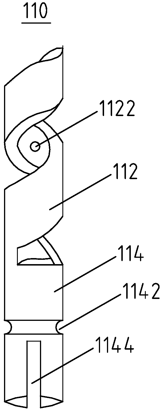
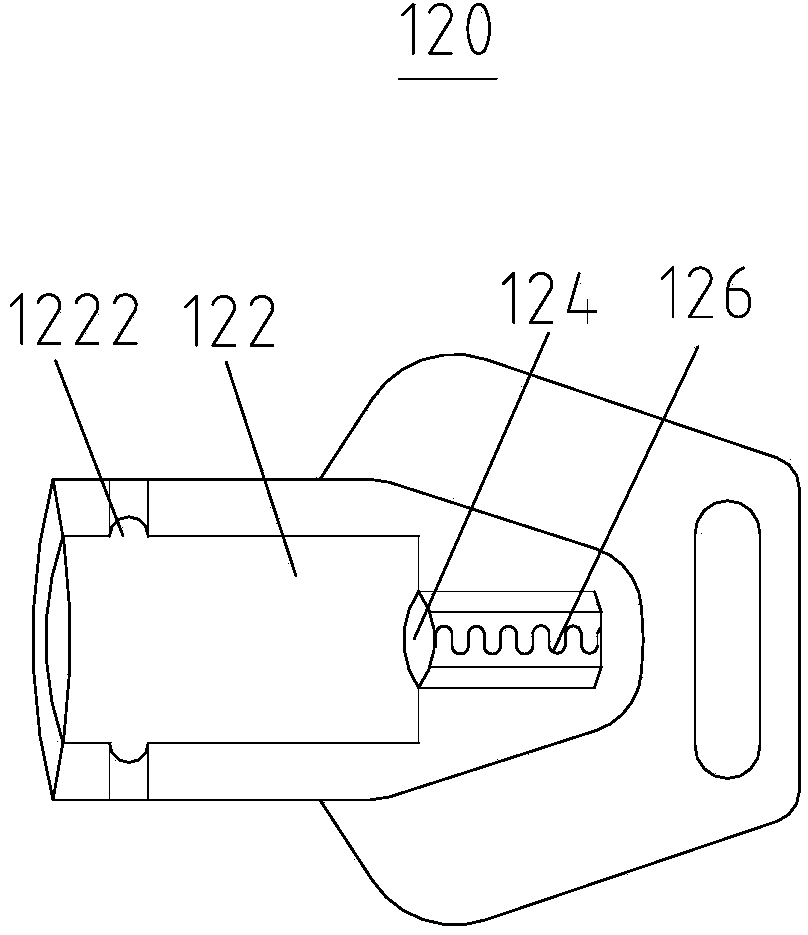
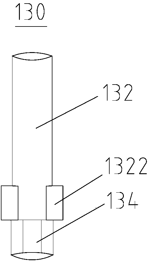
[0033] Such as Figure 1 to Figure 5 As shown, a screw key 100 includes a key head 110, a key handle 120, a connecting pin 130, and a ball 140. The key head 110 is a hollow structure, which includes a helical section 112 with a thread structure, and is connected to the helical section 112. The installation section 114, the inner surface of the helical section 112 is provided with a hole groove 1122, the outer surface of the installation section 114 is provided with a first rolling groove 1142, and the end of the installation section 114 away from the helical section 112 is provided with a limiting groove 1144, the connection pin 130 includes an insertion section 132 and a snap-in section 134 connected to the insertion section 132, the insertion section 132 is provided with a limiting portion 1322 near the outer surface of the snap-in section 134, and the insertion of the connection pin 130 The segment 132 is installed in the key head 110, the limiting part 1322 is stuck on the...
Embodiment 2
[0038] This embodiment provides a kind of lock, and its technical scheme is as follows:
[0039] Such as Figure 6 to Figure 8 As shown, a lock includes the above-mentioned screw key 100, a lock core 200, and a housing 300. The lock core 200 is a solid spiral column that matches the screw key 100, and the lock core 200 is installed in the housing 300. .
[0040] In the lock described in this embodiment, the screw key 100 cooperates with the solid spiral columnar lock core 200 to drive the lock core 200 to rotate in the housing 300 to realize locking and unlocking. The hole groove 1122 on the screw key 100 is equivalent to For the tooth flower, it is hidden on the inner surface of the spiral section 112, which effectively protects the tooth flower information. Paper, inkpad, plasticine and other tools cannot copy and copy the tooth flower information, avoiding the spiral key. 100 is illegally copied and copied, which greatly improves the safety of the lock, and the structure ...
PUM
 Abstract
Description
Claims
Application Information
 - R&D Engineer
- R&D Manager
- IP Professional
- Industry Leading Data Capabilities
- Powerful AI technology
- Patent DNA Extraction
Browse by: Latest US Patents, China's latest patents, Technical Efficacy Thesaurus, Application Domain, Technology Topic, Popular Technical Reports.
© 2024 PatSnap. All rights reserved.Legal|Privacy policy|Modern Slavery Act Transparency Statement|Sitemap|About US| Contact US: help@patsnap.com