Steel pipe arch bridge cable-stay connecting device and connecting method
A connecting device, the technology of steel tube arch bridges, applied in the direction of arch bridges, bridges, bridge construction, etc., can solve the problems of inability to adapt to the change of the angle of the buckle cable, uneven force, affecting the normal installation and use safety of the steel tube arch bridge, etc., to achieve reliable connection. , Uniform force, the effect of protecting the safety of hoisting
- Summary
- Abstract
- Description
- Claims
- Application Information
AI Technical Summary
Problems solved by technology
Method used
Image
Examples
Embodiment 1
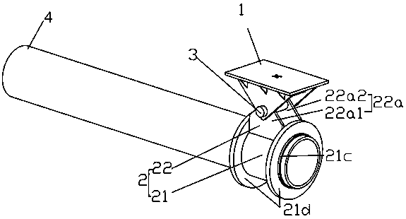
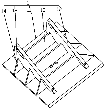
[0049] Such as figure 1 with image 3 As shown, the steel pipe arch bridge cable connection device includes a cable connector 1 for connecting with the cable. The steel pipe arch 4 is connected with a hoisting member 2 , and the hoisting member 2 is hinged to the cable connector 1 .
[0050] As one of the implementations, the lifting member 2 includes a fixed part 21, and a hinged part 22 connected to the fixed part 21, the fixed part 21 is connected to the steel pipe arch 4, and the hinged part 22 is connected by the rotating pin 3 Hinged with the buckle connector 1.
[0051] As one of the implementations, the fixed part 21 is a plurality of annular ribs 21a arranged on the outer wall of the steel pipe arch 4, and the plurality of annular ribs 21a are connected side by side to the outer wall of the steel pipe arch 4, and the hinged The part 22 is an ear plate 22a connected to a plurality of annular ribs 21a, and a plurality of annular ribs 21a are arranged on the outer wall...
Embodiment 2
[0064] The buckle cable coupling device of the steel pipe arch bridge of the present embodiment is basically the same as that of Embodiment 1, as figure 2 As shown, the difference lies in the structure of the fixing part 21. In this embodiment, the fixing part 21 is a sleeve 21c set on the outer wall of the steel tube arch 4, and the hinge part 22 is an ear plate 22a connected to the outer wall of the sleeve 21c.
[0065] The fixed part in the form of a sleeve structure is connected to the outer wall of the steel pipe arch, thereby increasing the contact area between the fixed part and the steel pipe arch, and ensuring that the hoisting member has a larger force range and is more uniform and reasonable during the process of hoisting the steel pipe arch.
[0066] Further, the outer wall of the sleeve 21c is connected with sleeve ribs 21d, and the sleeve ribs 21d are respectively arranged at both ends of the sleeve 21c, and the ear plate 22a is connected between the two sleeve r...
Embodiment 3
[0069] Steel pipe arch buckle cable connection method, such as figure 1 with figure 2 Shown, when adopting the fastening cable coupling device of embodiment 1 or embodiment 2 to connect and connect, comprise the following steps:
[0070] a. Connect the hoisting member 2 to the steel pipe arch 4;
[0071] b. Processing buckle connector 1;
[0072] c. Connect and fix the buckle cable on the buckle cable connector 1;
[0073] d. Lift the buckle connector 1 and the buckle to the target installation position, and insert the rotating pin 3 to complete the installation and connection of the buckle connector 1 and the hoisting member 2
[0074] e. Carry out tensioning of the buckle cable and complete the construction of the reorganized buckle cable.
[0075] Step a can also be performed after step c, and it is only necessary to connect the hoisting component to the steel pipe arch before installing the cable connector to the hoisting component.
[0076] In the above way, the hoi...
PUM
 Abstract
Description
Claims
Application Information
 - Generate Ideas
- Intellectual Property
- Life Sciences
- Materials
- Tech Scout
- Unparalleled Data Quality
- Higher Quality Content
- 60% Fewer Hallucinations
Browse by: Latest US Patents, China's latest patents, Technical Efficacy Thesaurus, Application Domain, Technology Topic, Popular Technical Reports.
© 2025 PatSnap. All rights reserved.Legal|Privacy policy|Modern Slavery Act Transparency Statement|Sitemap|About US| Contact US: help@patsnap.com


