Self-locking fast expanding sleeve pull-out device for connection of rocker arm device and grinding roll device

A self-locking and expanding sleeve technology, used in fixtures, mechanical equipment, grain processing, etc., can solve the problems of single structure, large impact load, aggravated economic losses, etc., to reduce safety risks, improve efficiency, and save costs. Effect

Pending Publication Date: 2018-03-27
中材(天津)粉体技术装备有限公司 +1
View PDF8 Cites 0 Cited by
  • Summary
  • Abstract
  • Description
  • Claims
  • Application Information

AI Technical Summary

Problems solved by technology

With the continuous development of vertical mills, the shafts of the grinding rollers are also thickened and lengthened, and the impact loads received during the operation of the equipment are also greater. Therefore, a larger pre-tightening force is required to install the shaft and the inner expansion sleeve into the outer expansion. The sleeve can ensure the normal operation of the equipment, but it is very difficult to disassemble the expansion sleeve during equipment maintenance. Generally, a special clamp is required to pull the inner expansion sleeve from the outer expansion sleeve.
The traditional expansion sleeve device connecting the rocker arm and the grinding roller shaft has a single structure and is cumbersome, requiring multiple people to dismantle and install the entire expansion sleeve device at the same time, and the parts are easily damaged during disassembly
The disassembly and installation of expansion sleeves belong to high-altitude operations, with high risk, long disassembly and assembly cycle, and the need for large-scale equipment, which not only brings a lot of inconvenience to users for maintenance and replacement, but also increases the damage caused by downtime. Economic losses

Method used


Image

  • Self-locking fast expanding sleeve pull-out device for connection of rocker arm device and grinding roll device
  • Self-locking fast expanding sleeve pull-out device for connection of rocker arm device and grinding roll device
  • Self-locking fast expanding sleeve pull-out device for connection of rocker arm device and grinding roll device

Examples


Embodiment Construction

[0029] In order to further understand the invention content, characteristics and effects of the present invention, the following examples are given, and detailed descriptions are as follows in conjunction with the accompanying drawings:

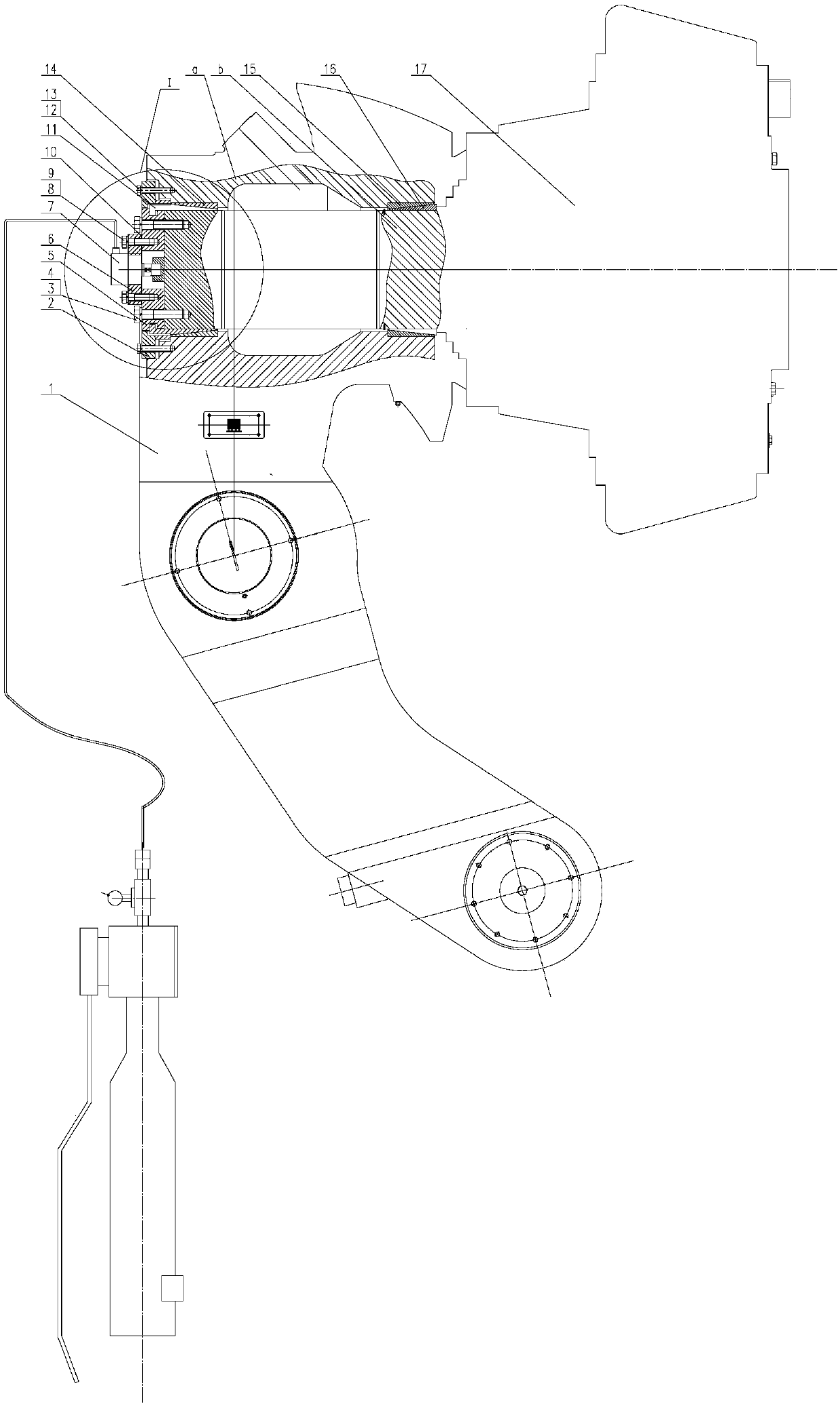
[0030] see Figure 1 to Figure 11 , a self-locking quick-lifting expansion sleeve device for connecting the rocker arm device and the grinding roller device,

[0031] The rocker device 1 includes an upper rocker a, and the grinding roller device 17 includes a grinding roller shaft b;

[0032] The upper rocker arm a is a hollow tubular structure, the grinding roller shaft b is inserted from the front hole of the upper rocker arm a, and reaches the rear end hole of the upper rocker arm a; include:

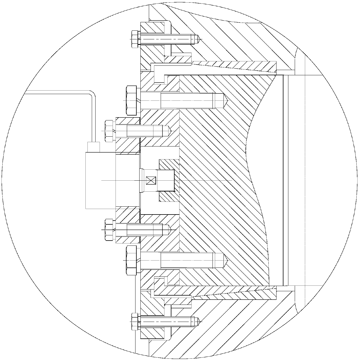
[0033] The front member located at the position of the front hole; the front member includes the front external expansion sleeve 15 and the front internal expansion sleeve 16 located between the outer wall of the grinding roller shaft b and the in...


PUM


Abstract

The invention discloses a self-locking fast expanding sleeve pull-out device for connection of a rocker arm device and a grinding roll device. The self-locking fast expanding sleeve pull-out device comprises a front component located at the position of a front end hole, and a rear component located at the position of a rear end hole. The front component comprises a front outer expanding sleeve anda front inner expanding sleeve located between the outer wall of a grinding roll shaft and the inner wall of an upper rocker arm. The rear component comprises a rear outer expanding sleeve, a rear inner expanding sleeve, an expanding sleeve outer gland and an expanding sleeve inner gland which are located between the outer wall of the grinding roll shaft and the inner wall of the upper rocker arm. The rear outer expanding sleeve is located on one side of the inner wall of the upper rocker arm, and the rear inner expanding sleeve is located on one side of the outer wall of the grinding roll shaft. The rear outer expanding sleeve and the rear inner expanding sleeve are in conical surface fit. The expanding sleeve outer gland and the rear end face of the upper rocker arm are fixedly connected. A through hole matched with the outer wall of the expanding sleeve inner gland is formed in the expanding sleeve outer gland. The inner diameter of the expanding sleeve outer gland is smaller thanthat of the upper rocker arm. The expanding sleeve inner gland is connected with the end face of the grinding roll shaft. A through hole to which a jack ejector rod inserted is formed in the expandingsleeve inner gland.

Description

technical field [0001] The invention relates to the technical field of grinding and grinding equipment for non-metallic solid materials, in particular to a self-locking quick-lifting expansion sleeve device for connecting a rocker arm device and a grinding roller device of a vertical roller mill (vertical mill for short). Background technique [0002] Vertical mill is an energy-saving grinding equipment widely used in cement, electric power, mining, steel and other industries. The vertical mill is a low-speed and heavy-duty equipment. The roller shaft and the rocker arm of the vertical mill must not only be able to maintain a tight connection during work, but also need to be able to replace the grinding roller bearings, seals, and rocker arm grinding roller wearing parts during maintenance. Quick separation, so in general, the expansion sleeve connection is used. With the continuous development of vertical mills, the shafts of the grinding rollers are also thickened and len...

Claims


Application Information

Patent Timeline
Patent Type & Authority Applications(China)
IPC IPC(8): B02C15/00B02C23/00F16B1/02
CPCF16B1/02B02C15/00B02C23/00
Inventor 李向阳申占民王文荟彭玉蓉
Owner 中材(天津)粉体技术装备有限公司
Why Eureka
Try Eureka