Wind power equipment with circumferential fixed structures

A circumferentially fixed, wind power equipment technology, applied in wind power generation, mechanical equipment, wind turbine combination and other directions, can solve the problems of local shaft overheating, impact, damage to connecting bolts, etc., to extend service life, improve economic benefits, improve use effect of life

Pending Publication Date: 2019-05-31
刘一峰
View PDF3 Cites 0 Cited by
  • Summary
  • Abstract
  • Description
  • Claims
  • Application Information

AI Technical Summary

Problems solved by technology

[0019] 1. Torsional fatigue fracture occurs on the main axis of the shafting system;
[0020] 2. The connecting parts in the shafting system, such as the connecting bolts of the shafting system, etc., are damaged and broken;
[0021] 3. Multiple torsional fatigue fractures occur on the connecting shafts of various accessories in the shaft system, such as oil pumps;
[0022] 4. The hub of the impeller and the connecting threaded fasteners of the main shaft are worn, loosened or broken;
[0023] 5. Local shaft overheating occurs in the shaft system;
[0024] 6. Causing disengagement-shock of the transmission gear of the speed-increasing gearbox or pitting corrosion and noise in the transmission part of the gear, so that the teeth are broken;
[0025] 7. Cause the rollers and balls of each rolling bearing to disengage from the cage, impact and damage;
[0026] 8. Serious loosening of various interference fits or red sleeve parts in the shafting system

Method used


Image

  • Wind power equipment with circumferential fixed structures
  • Wind power equipment with circumferential fixed structures
  • Wind power equipment with circumferential fixed structures

Examples


Embodiment 1

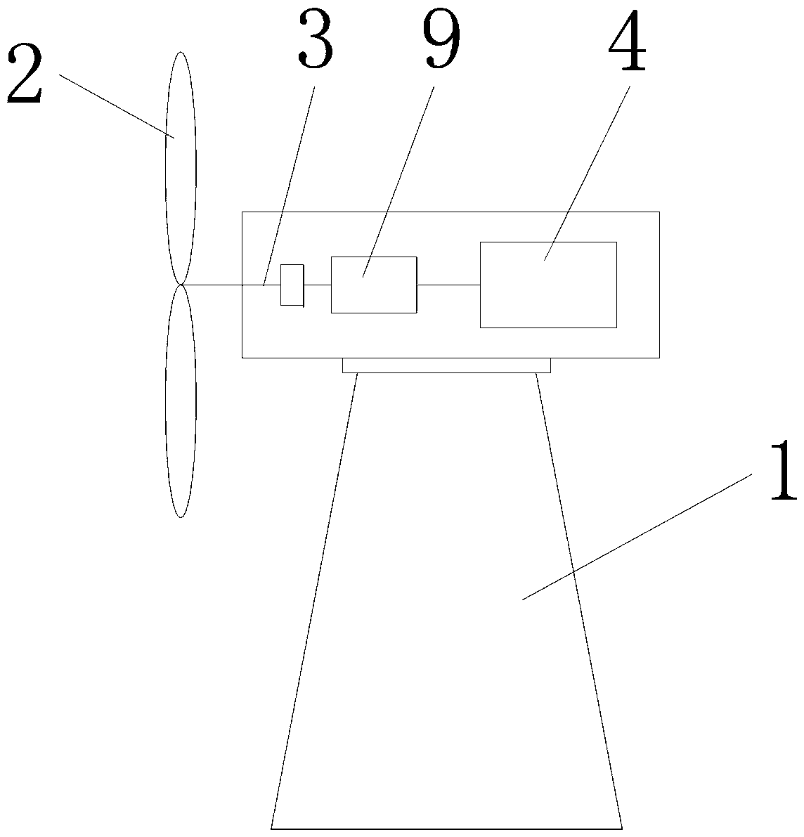
[0059] see Figure 2-4 , a (direct drive) wind power equipment without a gearbox, including a main shaft 3, a bearing 5 is arranged on the main shaft 3, the outer ring 7 of the bearing 5 is fixed to the bearing chamber in the circumferential direction, and the inner ring 6 of the bearing 5 is fixed to the main shaft 3 in the circumferential direction Fixed, wherein at least one of the outer ring 7 and the inner ring 6 is fixed circumferentially, so as to avoid the phenomenon of the bearing 5 running around due to vibration.

Embodiment 2

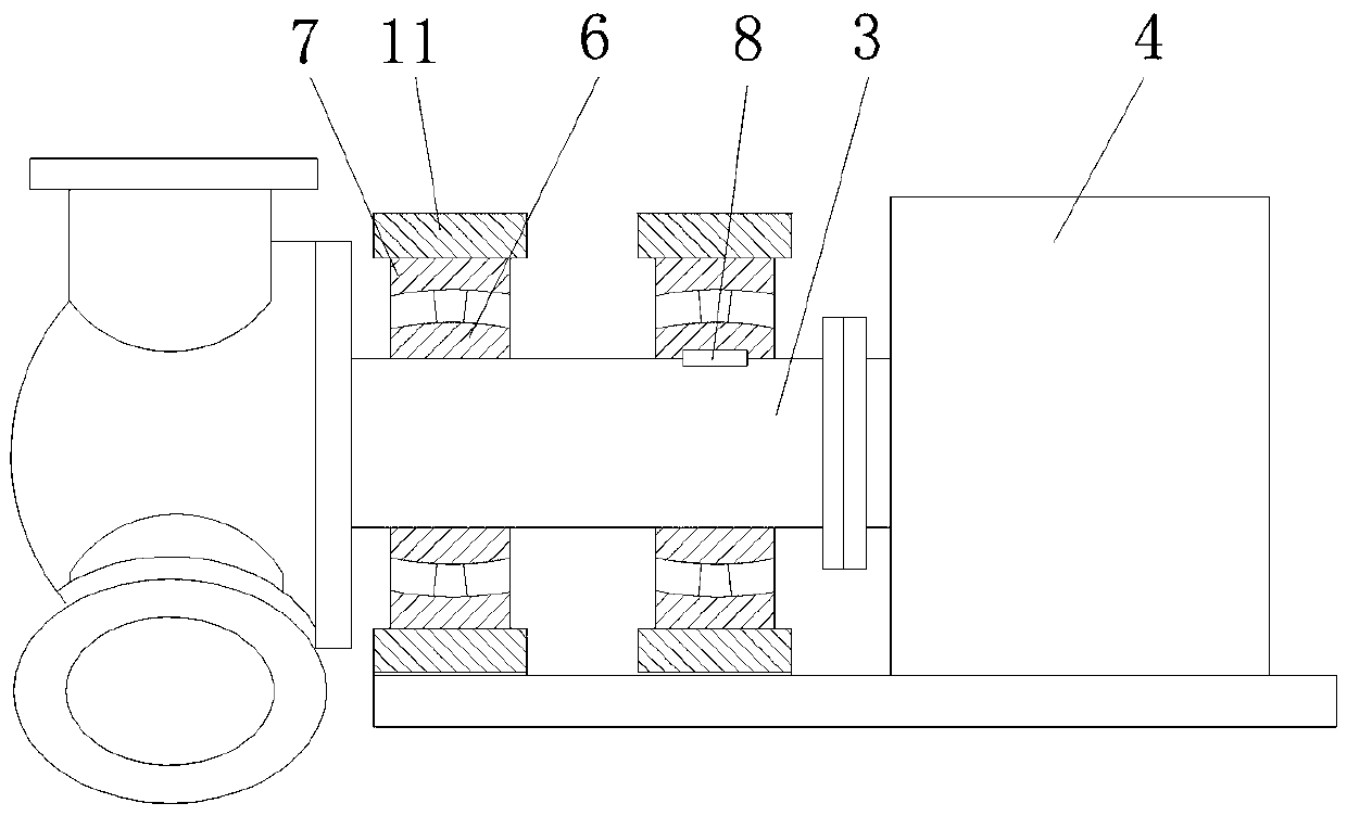
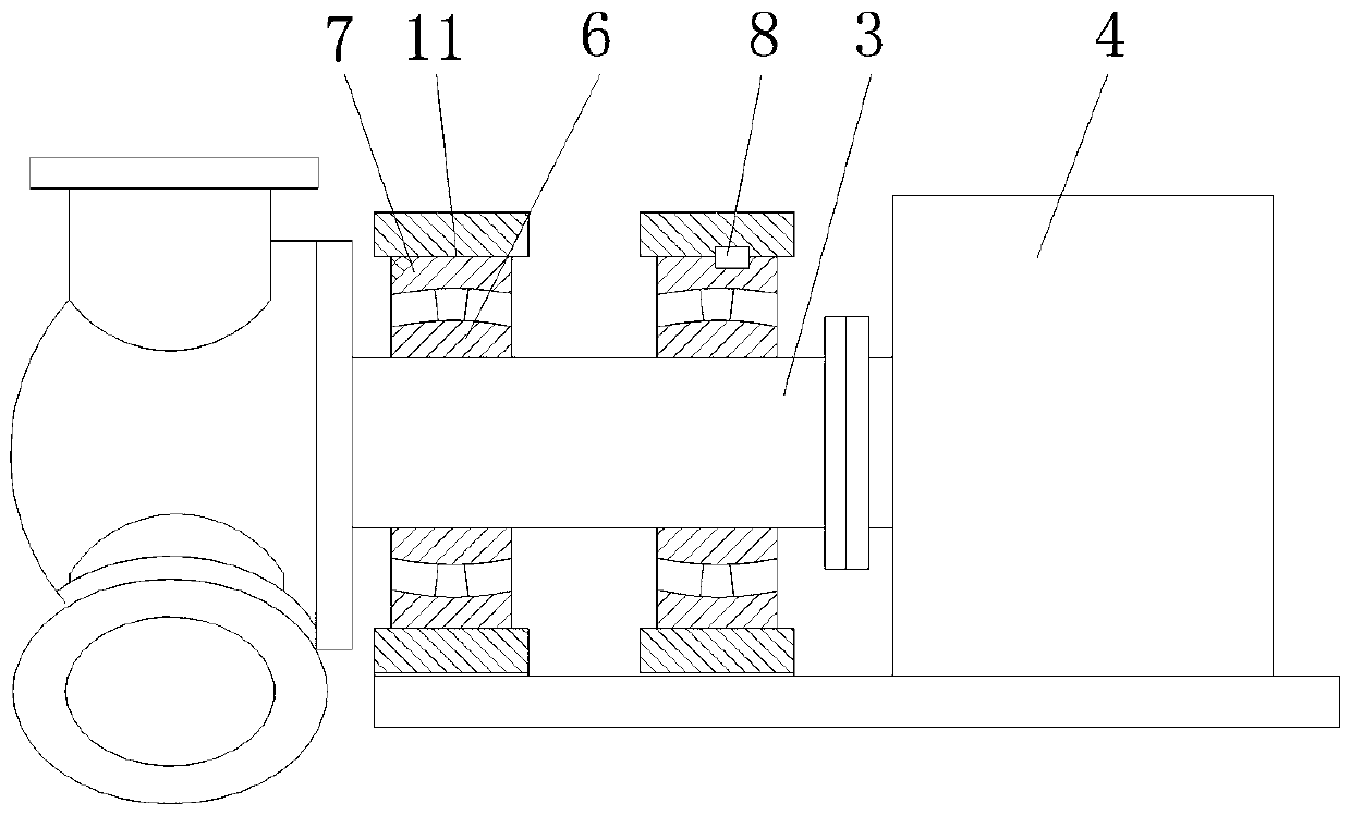
[0061] see Figure 5-Figure 8 , a wind power equipment with a gear box 9, including a gear box 9, a transmission shaft 10 in the gear box 9 and a bearing 5, at least one of the bearing 5 and the bearing chamber 11 outside the bearing 5 is provided with a circumferential fixed structure 8 .

Embodiment 3

[0063] see Figure 5-Figure 8 , a wind power equipment with a gearbox 9, including a gearbox 9, two transmission shafts 10 in the gearbox 9 and bearings 5, at least one of the bearings 5 ​​and the bearing chamber 11 outside the bearing 5 is provided with a circumferential fixing structure 8.


PUM


Abstract

The invention relates to wind power equipment with circumferential fixed structures. The wind power equipment comprises a tower. The top of the tower is mounted on a wind generating set. The wind generating set comprises an impeller. The impeller is in power connection with a main shaft. The main shaft is in power connection with a generator. Bearings are arranged at the front end and the rear endof the main shaft. Each bearing is composed of an inner ring, a roller, a holder and an outer ring. The circumferential fixed structures corresponding to the main shaft are arranged on the inner sides of the inner rings so that the inner rings and the main shaft can keep fixed, and the phenomenon of ring moving is avoided. The situation of bearing loosening is avoided through circumferential fixing of the bearings, and therefore equipment durability and the economic benefits of enterprises are improved.

Description

technical field [0001] The invention belongs to the technical field of wind power equipment, and relates to a wind power equipment with a circumferential fixed structure. Background technique [0002] Wind power equipment has been in a state of unprofitability. The main problem is that its installation and maintenance costs are too high. Since wind power equipment is installed in a high-lying place, the overall use environment is also relatively poor. Therefore, the low-frequency torsional vibration of the equipment often causes the bearing If problems such as looseness occur, the bearings generally adopt interference fit, red sleeve fixing or high-pressure jacking, but they will still loosen under long-term low-frequency torsional vibration, and the cost of bearing replacement on wind power equipment is very high, and a crane is required to lift , Each lifting requires a lot of manpower and financial resources, so the benefits generated by wind power equipment have been inv...

Claims


Application Information

Patent Timeline
Patent Type & Authority Applications(China)
IPC IPC(8): F03D9/25F03D80/70F03D15/00
CPCY02E10/72
Inventor 刘一峰
Owner 刘一峰
Why Eureka
Try Eureka