High power drainage pump-used motor

A technology for drainage pumps and motors, which is applied in the field of motors for drainage pumps and high-power drainage pumps. It can solve the problems of reducing the idling stroke of the starting rib, burning the motor, and small idling strokes, so as to solve the difficulty of starting and avoid starting. Effects of noise and starting voltage reduction

Inactive Publication Date: 2018-03-23
陈雪女
View PDF1 Cites 0 Cited by
  • Summary
  • Abstract
  • Description
  • Claims
  • Application Information

AI Technical Summary

Problems solved by technology

[0004] Because the starting rib will make a collision noise when it is in contact with the starting boss, in order to reduce this noise, shock absorbers can be respectively provided on both sides of the starting rib or the starting boss, but the above-mentioned existing structure has output The defects of small power and small starting torque are only applicable to some electrical drainage pumps with small power requirements and small flow requirements.
In particular, the addition of the shock absorber reduces the idling stroke of the starting rib. Because the idling stroke angle of the starting rib is small and the idling stroke is small, the starting torque is too small, and the shaft effect of the entire rotor system is not fully utilized. When When the load is heavy, it will be difficult to start. It needs to be started multiple times, resulting in multiple startup noises, or even failure to start. In severe cases, the motor will burn out, which cannot meet the needs of large-capacity and high-power electrical drainage pumps on the market.
[0005] At present, there is also a motor for drainage pumps on the market, which is controlled by electronic components to solve the problem of difficult startup. Specifically, a circuit board is added to the motor, that is, a controller, and the input current is adjusted by the controller. Realize the startup under different loads, but this startup method, because the price of the controller is relatively expensive, so the cost is relatively high

Method used


Image

  • High power drainage pump-used motor
  • High power drainage pump-used motor
  • High power drainage pump-used motor

Examples


Embodiment Construction

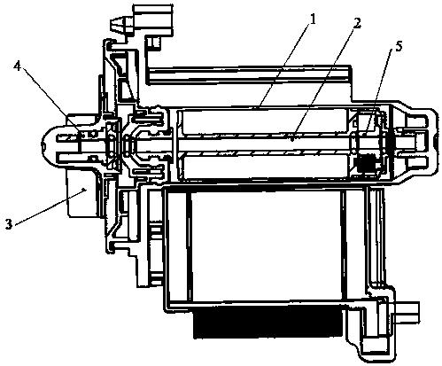
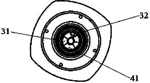
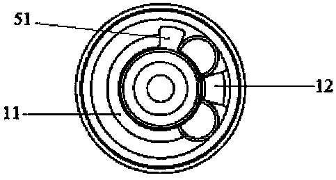
[0021] The structural schematic diagram of the specific embodiment of the present invention is as follows Figure 1-3 As shown, the motor for the high-power drainage pump includes a permanent magnet rotor 1, a motor shaft 2 and an impeller 3, an impeller coupling 4 is fixed on the motor shaft 2, and the impeller coupling 4 is activated by the impeller coupling 4. Rib 41, there is an impeller housing cavity 31 in the center of the impeller 3, which is used to accommodate the impeller coupling 4. The inner side wall of the impeller housing cavity 31 protrudes with an impeller limiting rib 32, and the impeller coupling starts the rib 41 to rotate forward or reverse. After turning a certain distance, it interferes with the impeller limiting rib 32; a rotor coupling 5 is also fixed on the motor shaft 2, and there is a rotor coupling starting rib 51 on the rotor coupling 5, and the permanent magnet rotor The magnetic core of 1 has a magnetic core accommodation cavity 11 for accommod...


PUM


Abstract

The invention discloses a motor for a high-power drainage pump. Starting structures are respectively arranged in the impeller housing chamber and the permanent magnet rotor magnetic core housing chamber. When the motor is started, the starting structure in the magnetic core housing chamber starts first, and the motor shaft Rotation, thereby driving the start-up structure in the impeller housing chamber to start, driving the impeller to rotate, and realizing the start-up of the motor. The idling stroke angle of the two starting structures is increased, which is beneficial to the starting of the motor for high-power drainage pumps, thereby avoiding the starting noise caused by multiple collisions caused by difficult starting. At the same time, the starting voltage is reduced, which can make the temperature rise of the motor lower. Safer and longer life.

Description

technical field [0001] The invention belongs to the technical field of household electrical appliances, and relates to a motor for a drainage pump, in particular to a motor for a high-power drainage pump used in household appliances such as washing machines and dishwashers. Background technique [0002] As we all know, household appliances such as washing machines and dishwashers usually need to drain the washing water through a drainage pump, which is usually a centrifugal drainage pump. In order to solve the problem of heavy load when the water pump is started, and it is easy to burn the motor, it is necessary to add a starting device. , so that the motor starts under no-load conditions, and after starting and rotating at a certain angle, the load is automatically connected to drive the impeller to rotate, which effectively solves the problem of burning the motor due to the large starting load. The starting device is mainly composed of a coupling provided with a starting r...

Claims


Application Information

Patent Timeline
IPC IPC(8): H02K7/00H02K7/14H02K7/10H02K1/27H02K5/24F04D13/06
CPCH02K7/003F04D13/06H02K1/27H02K5/24H02K7/10H02K7/14
Inventor 吴良
Owner 陈雪女
Why Eureka
Try Eureka