
Transverter energy consumption device control method and system

A technology of energy consumption device and control method, which is applied in the direction of power transmission AC network, etc., and can solve the problems of DC power grid absorption power redundancy, etc.

Inactive Publication Date: 2018-03-23
NR ELECTRIC CO LTD +1
View PDF4 Cites 11 Cited by
  • Summary
  • Abstract
  • Description
  • Claims
  • Application Information

AI Technical Summary

Problems solved by technology

[0005] The purpose of the present invention is to provide a control method and system for a converter energy-consuming device, which is used to solve the problem of absorbing power redundancy when the DC grid is disturbed after the new energy island wind farm is connected to the DC grid

Method used


Image

  • Transverter energy consumption device control method and system
  • Transverter energy consumption device control method and system
  • Transverter energy consumption device control method and system

Examples


Embodiment Construction

[0068] The implementation method of the present invention is described in detail below in conjunction with accompanying drawing: this implementation method is carried out under the condition taking the technical solution of the present invention as a premise, has provided detailed implementation mode and concrete operation process, but protection scope of the present invention does not Limited to the following examples.

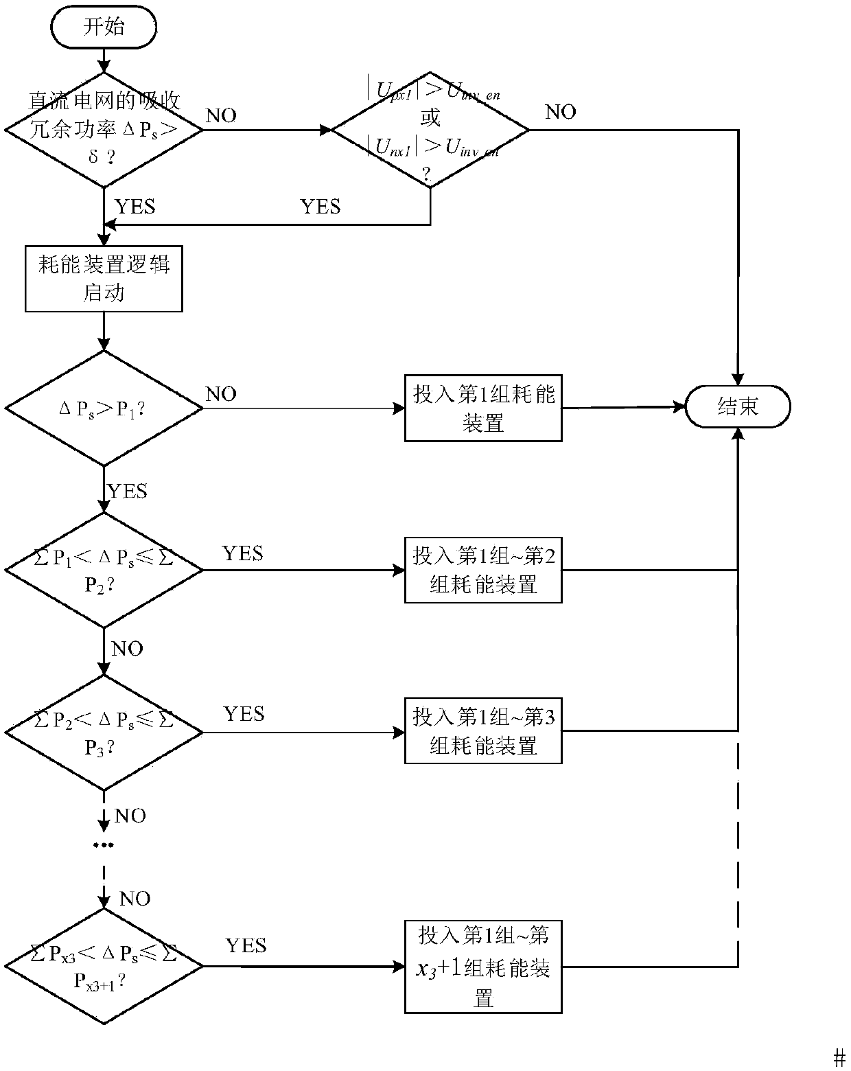
[0069] Applying the control method of a converter energy consumption device described in the present invention to figure 1 In the converter 1 topology shown, the converter 1 adopts a parallel structure with two AC sides, that is, a bipolar structure is formed by connecting the positive and negative converters in parallel. At the same time, an energy dissipation device is connected in parallel on the busbar on the AC side. The energy dissipation device consists of four groups of energy dissipation branches, and each group of energy dissipation branches is a pu...


PUM


Abstract

The invention relates to a transverter energy consumption device control method and system, and belongs to the field of direct current transmission. An energy consumption device controlled by the method and the system is composed of one or more sets of energy consumption branches and is arranged on the alternating current side of a sending end converter. When the working condition of a direct current network meets the input condition of the energy consumption device, the method and the system have the advantages that the number of the energy consumption devices put into the energy consumptionbranches is selected according to the magnitude of the redundant absorption power of the direct current network where the current converter is located. When the redundant power of the direct current network is cut off and meets the exiting condition of the energy consumption device, each set of the energy consumption branches sequentially exit. The system and method adopt a grouping strategy to realize the switching of the energy consumption devices, disturbance to the system can be reduced, and reliable operation of the non-fault converter during a system disturbance period is guaranteed.

Description

technical field [0001] The invention belongs to the technical field of flexible DC power transmission in power systems, and in particular relates to a control method and system for an energy consumption device of a converter. Background technique [0002] Flexible direct current transmission technology is an important technical means to realize multi-point collection of large-scale renewable energy, efficient utilization and flexible consumption of clean energy. Using flexible direct current transmission technology to achieve networking, stable operation under isolated islands or weak systems is an important aspect of renewable energy. An important prerequisite for flexible Internet access and consumption. However, the island electric field composed of clean energy such as wind power and photovoltaic is a very weak island, and it must be supported by AC voltage to operate normally. In the flexible direct current transmission project matched with the island wind farm, the fl...

Claims


Application Information

Patent Timeline
Patent Type & Authority Applications(China)
IPC IPC(8): H02J3/36
CPCH02J3/36Y02E60/60
Inventor 王佳成卢宇汪楠楠李钢董云龙胡兆庆姜崇学
Owner NR ELECTRIC CO LTD
Learn More