


Quick Research
Generate reliable direction feasibility study reports for your R&D in just a few steps.

Technical Q&A
Discover and master advanced knowledge NOW. Basics, ideas, possibilities, all at once.

Find Solutions
As an expert in R&D theories, this can generate solutions to your technical problems instantly.

Evaluate Feasibility
Analyze your overall solution with one click, know your potential R&D risks in advance.

Monitor Landscape
Get weekly tech updates, stay abreast of the latest tech innovations and key insights.
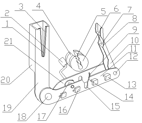
A temporary connection winder for electric construction cables
A temporary connection and electrical construction technology, applied in the direction of connection, line/collector parts, circuits, etc., can solve the problems of looseness, splashing of the insulating sheath, limited diameter range of the connector, etc., to reduce the stroke and improve the dredging efficiency. Effect
- Summary
- Abstract
- Description
- Claims
- Application Information
AI Technical Summary
Problems solved by technology
Method used
Image

Examples
Embodiment Construction
[0021] A temporary connection winder for electric power construction cables of the present invention is realized in the following way: when in use, put the two strands of power cords that need to be connected into the stripping groove (1) respectively, so that a certain length of the power cords is reserved in the storage slag Inside the box (20), slide the power cord along the skin cutter (3), cut off the insulation layer on the outer surface of the power cord, and then pull it to the outside of the slag storage box (20), so that the insulation layer falls off on the slag storage box (20 ), and then pass the two strands of metal wires through the waist-shaped holes on the auxiliary vertical plate (21), so that the two strands of wires are stuck in the waist-shaped holes through the insulating layer, and the connecting part of the metal wires passes through the winding rotor (6) The card slots (5) are arranged in sequence between the wave-shaped baffles (7) on the card slots (5...
PUM
 Abstract
Description
Claims
Application Information
 - R&D Engineer
- R&D Manager
- IP Professional
- Industry Leading Data Capabilities
- Powerful AI technology
- Patent DNA Extraction
Browse by: Latest US Patents, China's latest patents, Technical Efficacy Thesaurus, Application Domain, Technology Topic, Popular Technical Reports.
© 2024 PatSnap. All rights reserved.Legal|Privacy policy|Modern Slavery Act Transparency Statement|Sitemap|About US| Contact US: help@patsnap.com