Conformal load-bearing antenna structure for realization of array surface heat radiation by employing FSS and micro heat pipe
A micro-heat pipe and array technology, which is applied to antennas, antenna components, antenna grounding switch structural connections, etc., can solve the problems that the temperature changes of the wave-transparent cover and the filled core layer are greatly affected, and it is difficult to meet the antenna design requirements. Achieve the effect of improving structural and thermal functional properties and increasing structural rigidity
Active Publication Date: 2018-03-23
XIDIAN UNIV
View PDF6 Cites 9 Cited by
- Summary
- Abstract
- Description
- Claims
- Application Information
AI Technical Summary
Problems solved by technology
[0003] Phased array antenna front The dielectric skin and filling core layer of the traditional cover are integrated structure. In the phased array antenna front project, the antenna has strict temperature difference requirements (for example, the Ka frequency band requir
Method used
View moreImage
Smart ImageViewing Examples

Examples
 PUM
| Property | Measurement | Unit |
|---|---|---|
| Thickness | aaaaa | aaaaa |
Abstract
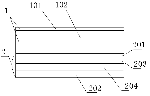
The present invention relates to a conformal load-bearing antenna structure for realization of array surface heat radiation by employing an FSS and a micro heat pipe. The conformal load-bearing antenna structure at least comprises: a wave-transparent cover body unit configured to bear an external load to protect an internal antenna; and an antenna unit. The wave-transparent cover body unit and theantenna unit are subjected to hot-pressing bonding by employing heat conduction materials to form a conformal load-bearing antenna structure. A heat radiation structure formed by the micro heat pipeand the frequency selective surface (FSS) is employed to form a cover body portion, the micro heat pipe is configured to transfer heat of the antenna array surface to the skinned FSS, so that the conformal load-bearing antenna structure can effectively increase the structure rigidity and intensity while employing external high-speed air flow to achieve heat radiation, facilitates improving of theCLAS structure and the heat function characteristic, and has a frequency selection wave-transparent characteristic.
Description
technical field [0001] The invention relates to a conformal load-carrying antenna, in particular to a conformal load-carrying antenna which utilizes FSS and miniature heat pipes to realize front heat dissipation. Background technique [0002] Conformal Load-bearing Antenna Structure (CLAS) is an antenna structure that has both the electromagnetic function of the antenna and the structural load-bearing function. It can be highly integrated with the shape of the carrier and has great application prospects. [0003] Phased array antenna front The dielectric skin and filling core layer of the traditional cover are integrated structure. In the phased array antenna front project, the antenna has strict temperature difference requirements (for example, the Ka frequency band requires the front temperature difference to be ≤3°C, X The front temperature difference in the frequency band is ≤7℃), the wave-transparent cover and the filling core layer are greatly affected by temperature c...
Claims
Login to View More Application Information
Patent Timeline
 IPC IPC(8): H01Q1/02H01Q1/42H01Q1/50
CPCH01Q1/02H01Q1/422H01Q1/50
Inventor 李鹏许万业宋立伟龚俊源陈磊黄进王从思李娜
Owner XIDIAN UNIV
Features
- R&D
- Intellectual Property
- Life Sciences
- Materials
- Tech Scout
- Unparalleled Data Quality
- Higher Quality Content
- 60% Fewer Hallucinations
Learn More Browse by: Latest US Patents, China's latest patents, Technical Efficacy Thesaurus, Application Domain, Technology Topic, Popular Technical Reports.
© 2025 PatSnap. All rights reserved.Legal|Privacy policy|Modern Slavery Act Transparency Statement|Sitemap|About US| Contact US: help@patsnap.com