an electric brake

A brake, electric technology, applied in the direction of brake, brake type, axial brake, etc., can solve the problems of wear, short service life, complex structure, etc., to achieve high control accuracy, simplify the structure, and ensure the effect of braking effect.

Active Publication Date: 2020-09-11
LONGZHONG HLDG GRP
View PDF4 Cites 0 Cited by
  • Summary
  • Abstract
  • Description
  • Claims
  • Application Information

AI Technical Summary

Problems solved by technology

[0004] The above-mentioned electromechanical brake uses the feed unit and compensation unit in the mechanical gap self-adjusting device to compensate the changed brake gap after braking, but the feed unit in the gap self-adjusting device includes non-self-locking nuts , the compensation unit includes structures such as non-self-locking bolts, piston cylinders, rectangular rings, and inner circlips. The entire gap self-adjusting device has many components, and the structure is relatively complicated. Abrasion occurs in the process of rotation, and the service life is short

Method used


Image

  • an electric brake
  • an electric brake
  • an electric brake

Examples


Embodiment Construction

[0030] The following are specific embodiments of the present invention in conjunction with the accompanying drawings to further describe the technical solutions of the present invention, but the present invention is not limited to these embodiments.

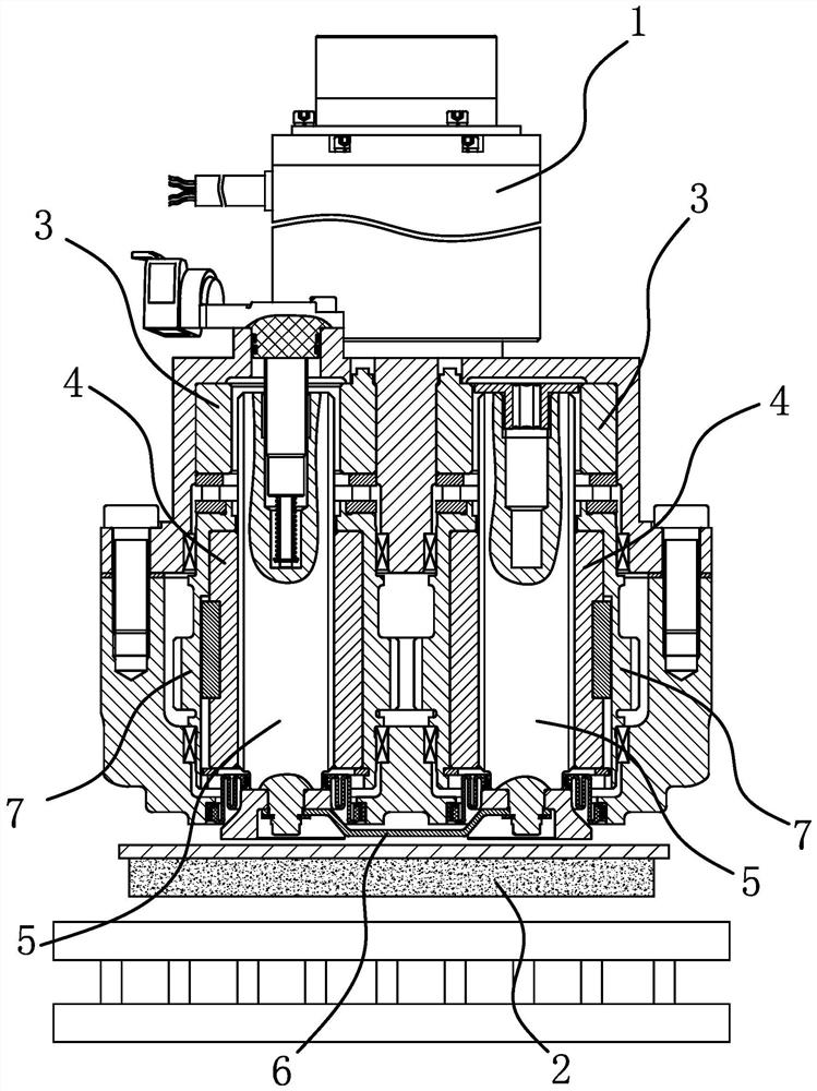
[0031] Such as image 3 As shown, the electric brake includes a drive motor 1, a screw drive structure, and a friction plate 2. The screw drive structure includes a transmission gear, a nut 4, a screw 5 threadedly connected to the nut 4, and a limit member 6, and the nut 4 is connected to the The output end of the driving motor 1 is in transmission connection, the limiting member 6 can limit the screw 5 in a circumferential direction, and one end of the screw 5 faces the friction plate 2. In this embodiment, both the nut 4 and the screw 5 are two. The outer sides of the two nuts 4 are both fixed with a ring gear 7 that can be connected to the transmission gear. The limit member 6 is plate-shaped and has two non-circular The cross-s...


PUM


Abstract

The invention provides an electric brake, and belongs to the technical field of automobiles. The problem that existing clearance self-adjusting devices are complex in structure is solved. The electricbrake comprises a driving motor, a screw transmission structure and a friction plate; the driving motor can drive the screw transmission structure to push the friction plate to abut against a brake disc of a vehicle; the driving motor can be driven by a controller to serve as a clearance compensation device to compensate the brake clearance of the electric brake, specifically, after the driving motor drives the screw transmission structure to start braking, a sensor is adopted to collect the braking force T1 borne by the friction plate when the friction plate abuts against the brake disc; thecontroller compares the collected braking force T1 with the preset braking force value T2, and when T1 is equal to T2, the position where a rotor of the driving motor is located is set to be the braking demarcation point; and after braking is finished, the braking demarcation point is used as an initial point, and the set reverse rotating number of turns N2 of the driving motor is controlled. Theelectric brake has the advantages of being simple in structure, high in control precision and good in braking effect.

Description

Technical field [0001] The invention belongs to the technical field of automobile braking and relates to an electric brake. Background technique [0002] Brake is a device with functions such as slowing down, stopping or maintaining a stopped state of moving parts (or moving machinery), commonly known as brakes. An electric brake is a type of brake. It uses a motor as a driving power source, and converts the circumferential rotation motion output by the motor into a linear motion through a mechanical transmission structure, thereby realizing the axial pushing of the friction plate. Compared with other brakes, electric brakes are gradually being widely used because of their advantages of energy saving, environmental protection, and easy integrated control. However, during the braking process, as the object of friction, the friction lining will continue to wear, so that the braking gap between the friction lining and the brake disc will gradually increase, so after the friction li...

Claims


Application Information

Patent Timeline
Patent Type & Authority Patents(China)
IPC IPC(8): F16D55/02F16D65/16F16D65/38B60T13/74F16D121/24
CPCB60T13/746F16D55/02F16D65/16F16D65/38F16D2055/0079F16D2065/386F16D2121/24
Inventor 肖水波罗少卿田鹏杨来科林聪付元念
Owner LONGZHONG HLDG GRP
Why Eureka
Try Eureka