


Quick Research
Generate reliable direction feasibility study reports for your R&D in just a few steps.

Technical Q&A
Discover and master advanced knowledge NOW. Basics, ideas, possibilities, all at once.

Find Solutions
As an expert in R&D theories, this can generate solutions to your technical problems instantly.

Evaluate Feasibility
Analyze your overall solution with one click, know your potential R&D risks in advance.

Monitor Landscape
Get weekly tech updates, stay abreast of the latest tech innovations and key insights.
Cylindrical forced water drainage pipe with circulated evacuation function, devices and methods
A drainage pipe and cylinder technology, applied in the field of foundation treatment and sludge dewatering, can solve the problem of high cost of dialysate and achieve the effect of preventing flattening
- Summary
- Abstract
- Description
- Claims
- Application Information
AI Technical Summary
Problems solved by technology
Method used
Image

Examples
Embodiment 1
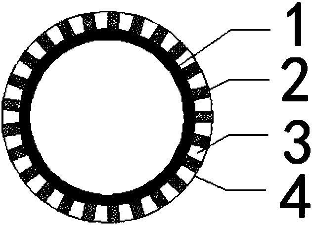
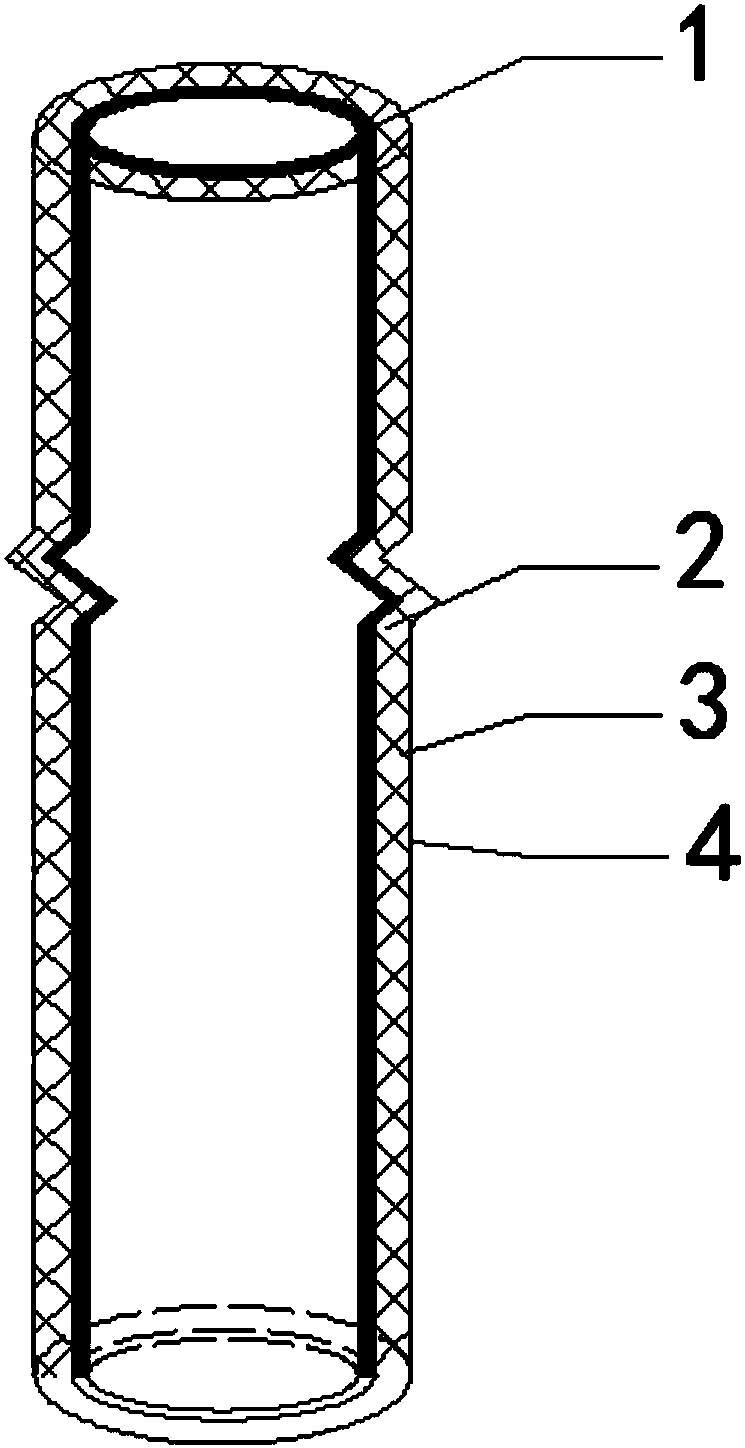
[0044] This embodiment provides a cylindrical strong drainage pipe with circulation emptying function, such as figure 1 , 2 As shown, it includes a pipeline 1 and a grid 2 arranged on the outer surface of the pipeline 1 along the axial direction of the pipeline 1 , and the outer surface of the grid 2 is covered with a filter membrane 4 .
[0045] In the above scheme, the outer surface of the grid 2 wraps the filter membrane 4 to form the drainage groove 3, and the distance between the grid 2 and the size of the grid 2 can be changed according to engineering needs to adapt to different geological conditions. At the same time, the pipeline 1 in the strong drainage pipe can also be used as the drainage pipeline 1, and the drainage groove 3 and the drainage pipeline 1 can be connected through the connection device to achieve the circulation function; the liquid stored in the strong drainage pipe can be quickly emptied by means of gas injection and the circular pipe is adopted It ...
Embodiment 2
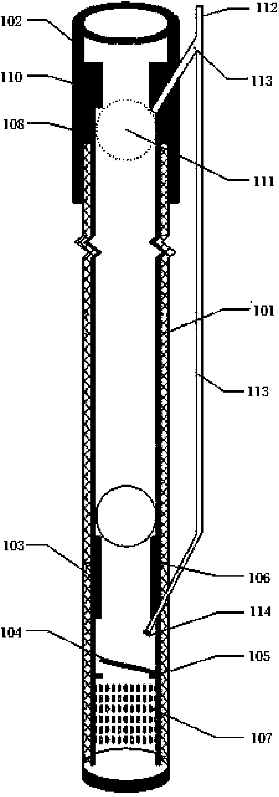
[0048] This embodiment provides a device for drainage consolidation of soft foundations, such as image 3 As shown, it includes the strong drainage pipe 101 described in Embodiment 1, the upper end joint 102, the lower end joint 103, the partition 104 and the fixing ring 105;
[0049] Wherein the lower end joint 103 is made of a section of strong drain pipe, and the lower end joint 103 is inserted into the upper end of the lower end joint 103 and the lower end of the strong drain pipe 101 through a cylindrical connector 106 with an outer diameter equal to the inner diameter of the strong drain pipe 101 pipe 101 to realize two The connection between the two, the grille 2 of the strong drain pipe 101 is aligned with the grille 2 of the lower end joint 103, and the lower end of the lower end joint 103 grille 2 and the lower end of the pipeline 1 are sealed; the lower end joint 103 of the pipeline 1 A through hole 107 is opened on the inner wall, and the grid 2 of the lower end jo...
Embodiment 3
[0062] This embodiment provides a sludge dewatering device, such as Figure 8~10 As shown, it includes a strong drainage pipe 101, an upper joint 201 and a lower joint 301; the lower joint 301 is made of a section of strong drainage pipe, and the filter membrane 4 of the lower joint 301 and the strong drainage pipe 101 is covered with a dialysis membrane 5; the lower joint 301 passes through A cylindrical connector 401 with an outer diameter equal to the inner diameter of the strong drain pipe 101 pipe 1 is inserted into the upper end of the lower joint 301 and the lower end of the strong drain pipe 101 to realize the connection between the two. The grid 2 of the strong drain pipe 101 is connected to the The grids 2 of the lower joint 301 are aligned one by one, and the lower end of the grid 2 of the lower joint 301 and the lower end of the pipeline 1 are sealed; It communicates with the pipeline 1 through the through hole 107; the upper joint 201 includes an inner tube 202 an...
PUM
 Abstract
Description
Claims
Application Information
 - R&D Engineer
- R&D Manager
- IP Professional
- Industry Leading Data Capabilities
- Powerful AI technology
- Patent DNA Extraction
Browse by: Latest US Patents, China's latest patents, Technical Efficacy Thesaurus, Application Domain, Technology Topic, Popular Technical Reports.
© 2024 PatSnap. All rights reserved.Legal|Privacy policy|Modern Slavery Act Transparency Statement|Sitemap|About US| Contact US: help@patsnap.com